1-2
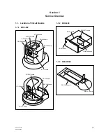
BRC-300/300P
BRU-300/300P
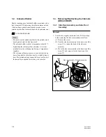
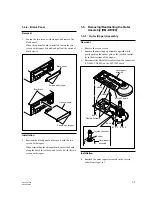
Side rear assembly
M2.6
x
4
Hook
Side front assembly
2
3
1
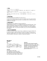
1-2. Unleaded Solder
Boards requiring use of unleaded solder are printed with a
lead free mark (LF) indicating the solder contains no lead.
(Caution: Some printed circuit boards may not come
printed with the lead free mark due to their particular size.)
: LEAD FREE MARK
m
.
Be sure to use the unleaded solder for the printed circuit
board printed with the lead free mark.
.
The unleaded solder melts at a temperature about 40
d
C
higher than the ordinary solder, therefore, it is recom-
mended to use the soldering iron having a temperature
regulator.
.
The ordinary soldering iron can be used but the iron tip
has to be applied to the solder joint for a slightly longer
time. The printed pattern (copper foil) may peel away if
the heated tip is applied for too long, so be careful.
1-3. Removing/Reattaching the Cabinets
(BRC-300/300P)
1-3-1. Side Rear Assembly and Side Front
Assembly
Removal
1.
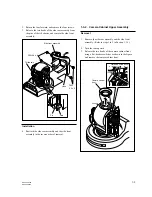
Turn the lens roughly backward in the PAN direction,
before removing the side rear assembly as follows.
(1) Remove the screw.
(2) Push the side front assembly in the direction of the
arrow
1
to release the hook of the side rear
assembly.
(3) Move the side rear assembly in the direction of the
arrow
2
, and remove it in the direction of the
arrow
3
.


