2-24
BRC-300/300P
BRU-300/300P
SW-1207 board
MC-66 board
DIP SW holder
PSW2
x
6
M3
x
6
M3
x
6
PSW2
x
6
CN4001
CN3503
CN4951
B3
x
5
Rear panel
SAS-101A
SAS-101A
K3
x
8
B3
x
5
B3
x
5
B3
x
8
B3
x
8
AC inlet
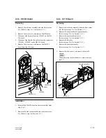
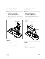
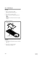
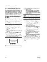
2-4-3. MC-66 Board and SW-120 Board
Removing
1.
Remove the cover panel.
(Refer to step 1 in Section 1-4-1.)
2.
Remove the slot assembly.
(Refer to steps 2 and 3 in Section 2-4-1.)
3.
Remove the optical transceiver SAS-101A as shown in
the figure.
4.
Remove the twelve screws, and remove the rear panel.
5.
Set the AC inlet to the outside of the chassis.
6.
Disconnect the harnesses from the connectors
(CN3503, CN4001) on the MC-66 board.
7.
Remove the five screws, and remove the MC-66
board.
8.
Disconnect the flexible flat cable from the connector
CN4951 on the MC-66 board.
9.
Remove the screw, and remove the SW-1207 board.
10. Remove the screw, and remove the DIP SW holder.
Installation
11. Reinstall the SW-1207 board to the MC-66 board in
the reverse order from steps 8 to 10.
12. Reinstall the MC-66 board in the reverse order from
steps 3 to 7.
13. Reattach the cover panel.
(Refer to step 2 in Section 1-4-1.)

