4-32
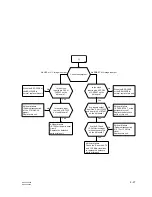
BRC-300/300P
BRU-300/300P
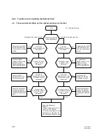
SD-50 BOARD (SIDE A)
R004
R048
R032
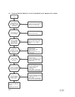
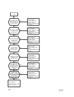
Does the unit
correctly function when
another BRBK-303 is
connected to the slot
on the main unit ?
No
Yes
Are the D3-pin level
of CN9001 on the MX
board and the R048
level on the EX board
set to “L” ?
Yes
BRC-300/P failure
Go to a-11.
BRU-300/P failure
Go to c-6.
No
MX board failure
(R9001, CN9001, or the
peripheral circuit)
Replace the defective
part or this unit.
Go to
6
(Next page)
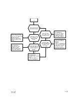
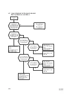
Does the unit
correctly function when
connected to a normal
BRC-300/P ?
Yes
BRBK-303 connection
failure
Connect this unit to
BRC-300/P securely.
No
Does the STANDBY
lamp on the BRC-300/P
light up while the
POWER switch on the
BRU-300/P is OFF ?
Yes
No
Turn on the POWER
switch of the BRU-300/P,
and check the
symptom.
Does
+
3.3 V exist in
pins C4, D4, E4 of
CN9001 and in pins 15,
16 of CN9002 on
the MX board ?
No
MX board failure
(L9006 to L9008, or the
peripheral circuit)
Replace the defective
parts or this unit.
Yes
Are the pin A6 level
of CN9001 on the
MX board and the
R004 level on the
EX board set to “L” ?
No
One of the following is
defective.
.
Laser unit
SAS-101A
.
CN9001 on the MX
board
Replace the SAS-101A
or this unit.
Yes
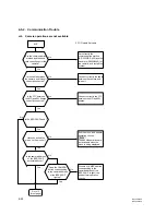
The BRC-300/P keeps the STANDBY status.
(The STANDBY lamp keeps lighting.)
Replace this unit when
the BRC-300/P or the
BRU-300/P is normal.
The message “communication error” appears on the
monitor, and the BRC-300/P returns to the STANDBY
status (the STANDBY lamp lights.).
g-1
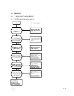
4-6-3. BRBK-303
g-1.
Image is not displayed.

