2-6
BRC-300/300P
BRU-300/300P
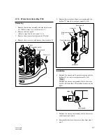
PSW2.6
x
6
PSW2.6
x
6
PSW2.6
x
6
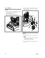
Spring (B)
Spring (B)
Spring (B)
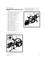
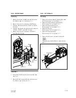
CN chassis assembly
Ferrite core
2-1-4. CN Chassis Assembly
Removing
1.
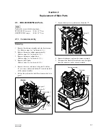
Remove the base plate. (Refer to Section 1-3-4.)
2.
Remove the SY-314 board.
(Refer to steps 2 to 4 in Section 2-2-11.)
3.
Remove the blank panel. (Refer to Section 1-3-5.)
4.
Remove the EXP chassis assembly and CC-91 board.
(Refer to steps 4 to 6 in Section 2-2-1.)
5.
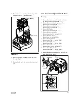
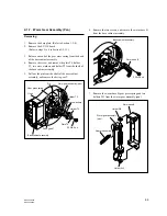
Remove the three springs (B).
6.
Remove the four screws, and then remove the CN
chassis assembly in the direction of the arrow.
7.
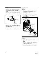
Remove the ferrite core from the harness shown in the
figure.
Installation
8.
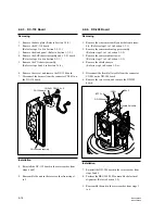
Reattach the CN chassis assembly in the reverse order
from steps 5 to 7.
9.
Reassemble the unit in the reverse order from steps 1
to 4.
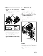
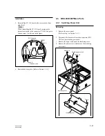
9 mm
28 mm
Tape
1
15 mm
15 mm
Tape
2
Tape
1
Tape
2
Video lens
Installation
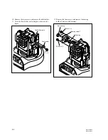
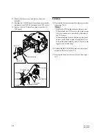
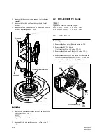
15. Affix the tape
1
and tape
2
to a new video lens.
n
For the tape
1
and tape
2
, cut the following part to
the size shown below, and then affix them.
Part No.: 3-076-631-01
16. Reattach the camera assembly in the reverse order
from steps 7 to 14.
17. Perform the BRC-300/300P camera block electrical
alignment. (Refer to Section 3-2.)
18. Reassemble the unit in the reverse order from steps 1
to 6.

