Sony XCG-CG160, Technical Manual
The Sony XCG-CG160 is a high-performance camera with exceptional image quality. Capture crisp and detailed images with ease using this cutting-edge device. Enhance your user experience by accessing the comprehensive user manual for free download at manualshive.com. Master your camera's unique features and unlock its full potential.
Share
Download


Reviews:
No comments
Related manuals for XCG-CG160
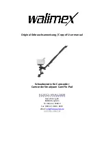
Steadycam Cam-Flo-Pod
Brand: walimex Pages: 7

Flip UltraHD
Brand: Cisco Pages: 9

SCOOPIC 16- M
Brand: Canon Pages: 41

SCOOPIC 16M
Brand: Canon Pages: 78

MVX430
Brand: Canon Pages: 129
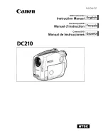
OC210
Brand: Canon Pages: 90
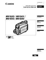
MV890
Brand: Canon Pages: 86

MVX4
Brand: Canon Pages: 147

MV690 E
Brand: Canon Pages: 225
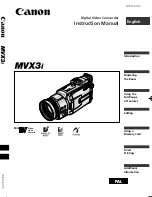
MVX3
Brand: Canon Pages: 174

MV6iMC
Brand: Canon Pages: 171

MV530
Brand: Canon Pages: 164

MVX-45i
Brand: Canon Pages: 157

mv880x
Brand: Canon Pages: 147

MV930
Brand: Canon Pages: 129

MV530i
Brand: Canon Pages: 164

MVX20i
Brand: Canon Pages: 164

MVX100
Brand: Canon Pages: 160


