4-18
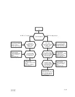
BRC-300/300P
BRU-300/300P
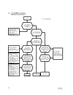
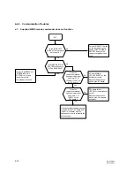
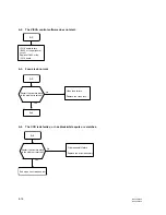
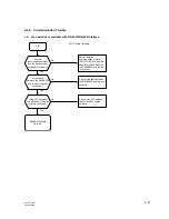
Are the laser unit
SAS-101A and the
CCFC-M100 correctly
connected ?
Is pin 107 of
IC3518 set to “H” and
the collector of Q4401
set to “L” ?
Yes
Is the AC adaptor
connected to the
BRC-300/P, and
supply AC power ?
No
Yes
The laser unit SAS-101A
failure
Replace the SAS-101A.
No
MC board failure
(IC3518, Q4401, or the
peripheral circuit)
Replace the defective parts or
the MC board.
Yes
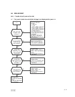
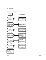
Is the connector of
CCFC-M100 clean ?
Yes
No
No
Is the 54 MHz
clock input to pin 8
of IC4401 ?
No
Yes
Remove the dirt or dust.
MC board failure
(X3001 or the peripheral circuit)
Replace the defective parts or
the MC board.
Connect the laser unit SAS-101A
and CCFC-M100 securely.
Connect the AC adaptor to the
BRC-300/P, and supply AC
power.
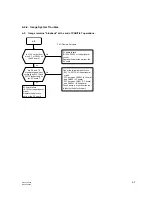
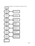
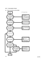
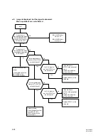
Does
+
3.3 V exist
in pins 15, 16 of CN 4401
on the MC board ?
No
Yes
One of the following is defective.
.
L4403 to L4405, or the
peripheral circuit
.
+
3.3 V line
Check above in order from the
top to identify the defective part.
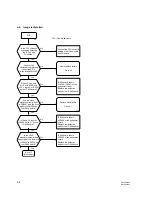
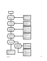
Is
+
2.5 V power
supplied to IC4401 on
the MC board ?
No
Yes
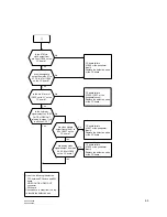
One of the following is defective.
.
L4406, or the peripheral circuit
.
+
2.5 V line
Check above in order from the
top to identify the defective part.
c-2
c-2.
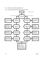
The power indicator blinks in red, and “communication error” appears on the monitor.

