1-4
BRC-300/300P
BRU-300/300P
4.
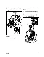
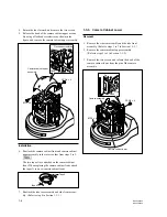
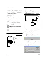
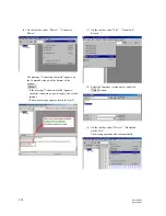
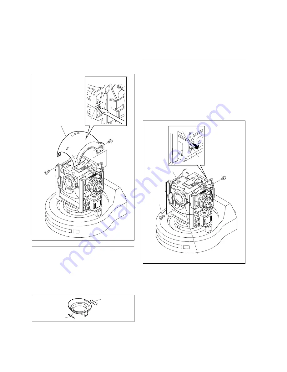
Return the lens forward, and remove the two screws.
5.
Release the hook of the camera cabinet upper assem-
bly using a flat-head screwdriver as shown in the
figure, and remove the camera cabinet upper assembly.
Installation
6.
Reattach the camera cabinet front and camera cabinet
upper assembly in the reverse order from steps 2 to 5.
n
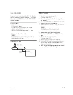
The two tapes A are attached on the camera cabinet
front. When replacing the camera cabinet front, attach
the tapes A to a new camera cabinet front.
7.
Reattach the side rear assembly and side front assem-
bly. (Refer to step 4 in Section 1-3-1.)
1-3-3. Camera Cabinet Lower
Removal
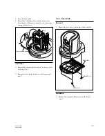
1.
Remove the side rear assembly and the side front
assembly. (Refer to steps 1 to 3 in Section 1-3-1.)
2.
Remove the camera cabinet upper assembly.
(Refer to steps 2 to 5 in Section 1-3-2.)
3.
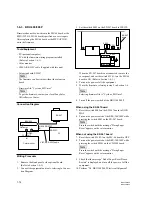
Remove the two screws, and release the hook of the
camera cabinet lower from the pin of the camera
assembly.
Camera cabinet upper
assembly
BTP2
x
6
PSW2
x
6
Flat-head screwdriver
Hook
BTP2
x
6
PSW2
x
6
Camera assembly
Camera cabinet lower
Hook
Pin
Hole
Tape A
Tape A

