


3-32
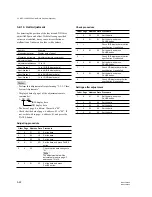
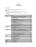
BRC-300/300P
BRU-300/300P
A
NTSC
PAL
A
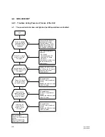
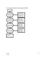
BRC-300/300P
EX-947
board
S002
ADJ
OPE
S002
BRC-300/300P
EX-947
Card slot
CN001
75
Z
75
Z
VIDEO
OUT
EXT. SYNC IN
TG-7
Frequency counter
SC OUT
IN
IN
IN
OUT
OUT
Waveform monitor
Color monitor
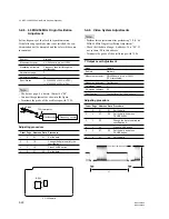
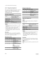
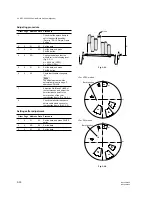
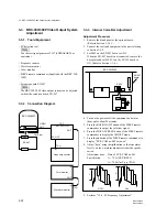
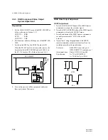
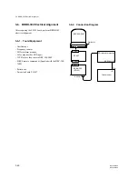
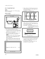
3-3. BRC-300/300P Video Output System Adjustment
3-3-3. Internal Color-Bar Adjustment
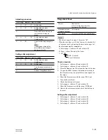
Adjustment Procedure
1.
Remove the blank panel or the optional board.
(Refer to Section 1-3-5.)
2.
Connect the tools and equipment to the unit, referring
to Section 3-3-2.
3.
Set S002 on the EX-947 board to ADJ.
When the EX-947 board is not connected, remove the
base plate and set S1003-3 on the SY-314 board to
ON. (Refer to Section 1-3-4.)
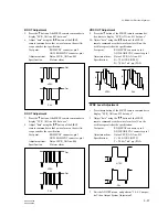
4.
Turn on the power of all the equipment, and warm
them up for about 20 minutes.
5.
Press the BACK LIGHT button of the SIRCS remote
commander to output the color-bar signal.
6.
Press the DATA SCREEN button of the SIRCS remote
commander to display the ADJUST menu.
7.
Press the button of the SIRCS remote commander to
display “EVR_CAM no:002 data:xxx”.
8.
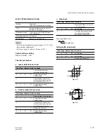
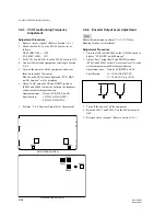
Adjust “data” using the / button so that waveform
level A on the waveform monitor satisfies the specifi-
cation.
Adjustment item:
Data of EVR_CAM no:002
Specification:
A = 75
±
1 IRE (NTSC)
A = 700
±
7 mV p-p (PAL)
9.
Perform “3-3-4. SC Frequency Adjustment”.
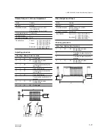
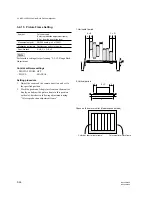
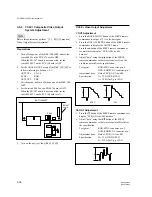
3-3. BRC-300/300P Video Output System
Adjustment
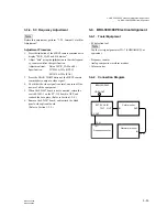
3-3-1. Tools/Equipment
.
SC detection tool
n
Use the test signal generator TG-7 (SHIBASOKU) or
equivalent.
.
Frequency counter
.
Waveform monitor
.
Color monitor
.
SIRCS remote commander (Supplied with the BRC-300/
300P)
.
Extension board EX-947
n
The BRC-300/300P video output system can be adjusted
without the extension board EX-947.
3-3-2. Connection Diagram


