3-7
BRC-300/300P
BRU-300/300P
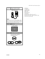
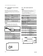
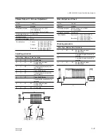
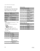
Color bar chart standard picture frame
H
A
B
A = B
B
A
0
±
0.1 ms
V
Enlargement
Difference in level
A
B
Electronic beam
scanning frame
CRT picture frame
Fig. b. (Color monitor picture)
Yellow
Cyan
Green
White
Magenta
Red
Blue
Yellow
Cyan
Green
White
Magenta
Red
Blue
Fig. a. (Video input/output terminals
output wavefom)
Adjust the camera zoom and direction to obtain the output waveform
shown in Fig. a. and the TV monitor display shown in Fig. b.
3-2-4. Precaution
1. Adjusting Procedure
Perform the adjustments continuously from Sections 3-2-8 to 3-2-21 in order.
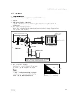
2. Subject
(1) Color-bar chart (Standard picture frame)
Adjust the picture frame as shown in the following figure if adjustments are performed using the
color-bar chart.
(2) White pattern (Standard picture frame)
Remove the color-bar chart from the pattern box, and insert a clear chart in its place. (Do not perform
zoom operations during this time.)
841 mm
1189 mm
White
Black
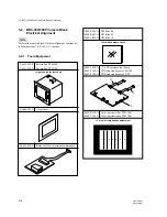
3-2. BRC-300/300P Camera Block Electrical Alignment
(3) Chart for flange back adjustment
Combine a white A0 size (1189 mm
x
841 mm) paper
to a black one, and make the chart shown in right
figure.
n
Use the non-reflecting and non-glazing vellum paper
whose size is more than A0, and make the boundary
between white and black to be smoothly flat.


