Sony 10001, Service Manual
The Sony 10001 Operation Manual is available for free download on our website. This comprehensive manual provides step-by-step instructions and essential information needed to operate your Sony 10001 product effectively. Find and download this manual effortlessly at manualshive.com to enhance your product experience.
Share
Download


Reviews:
No comments
Related manuals for 10001

XA11
Brand: Canon Pages: 4

Legria mini
Brand: Canon Pages: 2

RM-Lite 1.0
Brand: Canon Pages: 163

MVX300
Brand: Canon Pages: 8

PICTBRIDGE DC22
Brand: Canon Pages: 3

Legria HF G25
Brand: Canon Pages: 38

VIXIA HF G10
Brand: Canon Pages: 184
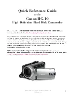
HG-10
Brand: Canon Pages: 20
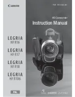
LEGRIA HF R16
Brand: Canon Pages: 172

Pixma G1000 series
Brand: Canon Pages: 72

FS200 - Camcorder - 680 KP
Brand: Canon Pages: 2

SCOOPIC 16- M
Brand: Canon Pages: 39

SCOOPIC 16- M
Brand: Canon Pages: 25
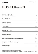
EOS C300 Mark II
Brand: Canon Pages: 42

E200 Series
Brand: Canon Pages: 84

FS30
Brand: Canon Pages: 116
VIXIA HF M30
Brand: Canon Pages: 26

VP-D73
Brand: Samsung Pages: 170


