Sony 10001, Installation Manual
The Sony 10001 Operation Manual is available for free download on our website. This comprehensive manual provides step-by-step instructions and essential information needed to operate your Sony 10001 product effectively. Find and download this manual effortlessly at manualshive.com to enhance your product experience.
Share
Download


Reviews:
No comments
Related manuals for 10001

CINECAM AHDVC01F
Brand: Aluratek Pages: 2
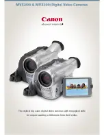
MV MVX250i
Brand: Canon Pages: 8

MV 100
Brand: Canon Pages: 86

Legria HFR76
Brand: Canon Pages: 8

MV MV600
Brand: Canon Pages: 8

MV MV700
Brand: Canon Pages: 8

MV400
Brand: Canon Pages: 116
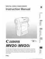
MV 20 i
Brand: Canon Pages: 116

MV 300 i
Brand: Canon Pages: 112

LEGRIA HF21
Brand: Canon Pages: 184

MV 30
Brand: Canon Pages: 122
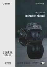
Legria HFG30
Brand: Canon Pages: 184

LEGRIA HFM40
Brand: Canon Pages: 196

LEGRIA HV40
Brand: Canon Pages: 108
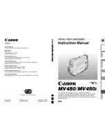
MV450
Brand: Canon Pages: 153

Legria HFG10
Brand: Canon Pages: 180

Legria hfm300
Brand: Canon Pages: 203

Legria HFM52
Brand: Canon Pages: 241


