


9 - 19
9. TROUBLESHOOTING
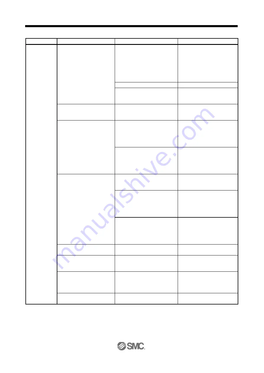
Phenomena
Checkpoint
Estimated cause
Action
The servo motor
does not operate.
Check the cumulative command
pulses with the status display or
software (MR Configurator2
TM
).
The display does not change even
if the pulse train command is input.
The wiring of the command pulse
train signal is incorrect.
Check the type of the command
pulse train (the differential receiver
system or the open collector
system).
Supply an external power (24VDC)
between OPC and DOCOM for the
open collector system.
The command pulses are not input.
Review the driver setting.
The settings of the parameter
No.PA13 (command pulse input form)
are incorrect.
Set the same value as the pulse
output form of the driver.
Check the settings of the
parameter No.PA01 (control
mode).
The settings of the parameter
No.PA01 (control mode) are incorrect.
Review the settings of the
parameter No.PA01 (control mode).
Check that the generated torque
does not exceed the torque limit
value.
1. Check "instantaneous
occurrence torque" with "status
display".
2. Check the torque ripple with the
"Graph" command on the
"Monitor" menu on software
(MR Configurator2
TM
).
1. The maximum torque is lacking.
The servo capacity is lacking. Or
the load is too large.
1. Change the mass or the shape of
the work to reduce the load.
2. Make the acceleration/
deceleration time shorter to make
the effective load ratio lower.
2. Unintended torque limit is valid. Or
the setting of the torque limit is 0
(no generating torque).
(Set with the parameter No.PA11/
PA12/PC35.)
Review the torque limit setting.
Check the status of the analog
input voltage.
1. Check with the status display.
2. Check with the "Display all"
command on the "Monitor"
menu on software (MR
Configurator2
TM
).
<Position control mode>
The input voltage of the analog
torque limit (TLA) is incorrect.
Review the settings of the analog
torque limit (TLA) and the analog
input voltage.
<Speed control mode>
The input voltage of the analog
speed command (VC) or that of the
analog torque limit (TLA) is
incorrect.
Review the settings of the analog
speed command (VC), the analog
torque limit (TLA) and the analog
input voltage.
<Torque control mode>
The input voltage of the analog
torque command (TC) or that of the
analog speed limit (TLA) is
incorrect.
Review the settings of the analog
torque command (TC), the analog
speed limit (VLA) and the analog
input voltage.
Check that machine interference
occurs.
Machine interference occurs.
Eliminate the machine interference.
Check the power supply for the
servo motor with an
electromagnetic brake.
The electromagnetic brake is not
released.
Turn the electromagnetic brake
power on to release the brake.
The ABSM signal is on while the
absolute position detection system
is used.
1. The driver operates in the ABS
transfer mode.
2. The absolute position data transfer
is not complete.
Set the driver setting (parameter
No.PA03), wiring and ladder
program of the driver properly.
Check the electronic gear settings. The electronic gear settings are
incorrect.
Set the proper electronic gear.
Содержание LECSB Series
Страница 1: ...PRODUCT NAME AC Servo Motor Driver MODEL Series LECSB Series Doc no JXC OMT0021 B ...
Страница 17: ...7 App 6 Compliance with the European EC directives App 7 App 7 Conformance with UL C UL standard App 10 ...
Страница 255: ...10 1 10 OUTLINE DRAWINGS 10 OUTLINE DRAWINGS 2 10 1 Driver 2 10 2 Connector 4 ...


