Manual - TC.P Quadro
TopControl application
2016-08-05
244/330
V04.52
6
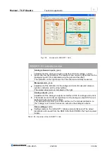
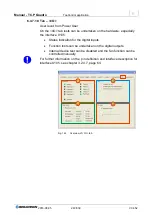
<I/O> tab
– parameter overview
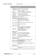
1
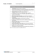
Digital inputs,
group with status read-only indications
Depending on the status
Green
≙
Connected
Grey
≙
Not connected
Interlock
Pin name on the interface: INTERL
Digital input 1-4 Pin name on the interface: APP_DIGITALIN_1-4
Debug In 1-4
Only for use by the manufacturer!
Flash Ready
Only for use by the manufacturer!
Voltage on
Pin name on the interface: VOLTAGE_ON
2
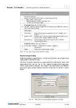
Digital outputs,
group with check boxes
Manual output control
is selected (manual operation)
The LEDs no longer indicate the device status
Digital outputs are no longer operated
The LEDs on the front panel are turned on using check
boxes.
The internal LEDs on the controller board are turned on using check
boxes.
The digital outputs are operated using check
boxes.
External (front) LED:
Power LED “POWER”; Status LED “STATUS”;
Error LED “ERROR”; CV LED “ VOLTAGE”;
CC LED “CURRENT”; CP LED “POWER”
Internal LED:
Life LED; Exception LED
Only for use by the manufacturer!
LEDs on the controller board.
Digital outputs:
Warn Relais
Pin name on the interface: WARN_a/b/c
OK/Alarm Relais Pin name on the interface: OK/ALARM_a/b
Run Relais
Pin name on the interface: RUN_a/b
Debug Out 0-2 Only for use by the manufacturer!
Internal test points on the controller board.
3
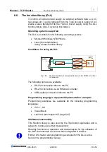
Tests,
group with check boxes
Disable DC link test
Disable the intermediate circuit voltage monitoring.
Disable output current underrange test
Disable the negative output current monitoring.
Disable output current overrange test
Disable the AD measuring range limit monitoring for the
output current.
4
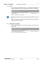
Fan speed,
group
Manual fan control
If selected, the speed of the fan can be controlled manually
using the slide.
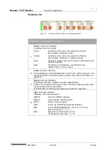
Table 145 Parameters on the <I/O> tab
– some parameters relate to interface X105, chapter
.


