Manual - TC.P Quadro
TopControl application
2016-08-05
206/330
V04.52
6
4
5
6
1
2
3
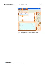
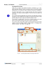
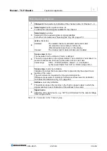
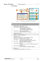
Fig. 122
Overview of the <SCOPE> tab.
<SCOPE> tab
– overview
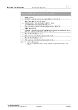
1
Scope display
Indication of the signals that have been detected on the related channels
-2-
.
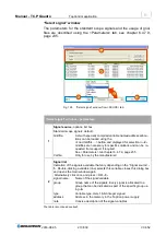
The values recorded can be zoomed and measured on the screen. See
“Scope display” group Fig. 123, page 207.
2
Channel selection
4 channels are available that can be indicated simultaneously on the display
-
1-
. Signals for recording can be defined in each channel. See “Channel” group
3
Control,
group
Triggering the measuring process, saving/loading the scope configuration and
the values to be recorded. See “Control” group Fig. 129, page 218.
4
Trigger,
group
Define the trigger signal, the trigger level and any delay as well as the trigger
edge on a signal. See Fig. 130, page 220.
5
Time resolution/sampl. Points,
groups
Expansion of the measurement along the time axis and definition of the accu-
racy by means of the number of points.
6
Status/Cursor,
groups
Status indication for the scope and indication of the cursor position.
Table 118 <SCOPE> tab
– overview.

