Manual - TC.P Quadro
TopControl application
2016-08-05
230/330
V04.52
6
1
2
3
4
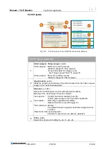
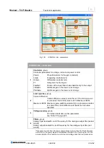
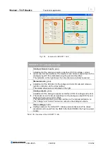
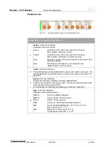
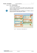
Fig. 137
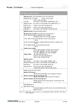
<PROTECT> tab
– parameters.
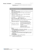
<PROTECT> tab
– parameters
1
Overvoltage,
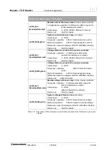
overvoltage with following text boxes
Error limit
Threshold from which the device switches to the error state.
Value range [V]: 0
– 1.1 *U
NOM;
Error delay
Min. period for which the error limit must be exceeded before
the device switches to the error state.
Value range [ms]: 0
– 1638.35;
Warn limit
Threshold from which the device switches to the warning state.
Value range [V]: 0
– 1.1 *U
NOM;
Warn delay
Min. period for which the “Warn limit” must be exceeded
before the device switches to the warning state.
Value range [ms]: 0
– 1638.35;
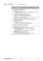
2
Overcurrent,
overcurrent with following text boxes
The meaning is similar to the boxes in
-1-.
Error limit
Value range [A]: 0
– 1.1 *I
Max;
Error delay
Value range [ms]: 0
– 1638.35;
Warn limit
Value range [A]: 0
– 1.1 *I
Max;
Warn delay
Value range [ms]: 0
– 1638.35;
3
I
2
t,
with following text boxes
For explanation and example calculation see “Example I2t parameter , page 229
Current inom
Nominal value for the load connected
Error limit
Threshold that causes an overcurrent error.
Value range is device-dependent. (time value required)
Warn limit
Threshold that causes an overcurrent warning.
Value range is device-dependent. (time value required)
4
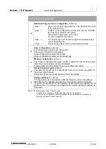
Store settings
, button
Settings made on the <PROTECT> tab are permanently saved. The actual pa-
rameter set is saved from the RAM to the flash PROM in the TopCon power sup-
ply.
Table 138 Error and warning thresholds on the <PROTECT> tab.

