First Steps with the Instrument
R&S
®
SGT100A
39
User Manual 1176.8674.02 ─ 07
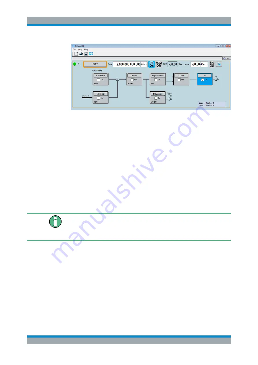
The 2 GHz signal is output at the RF OUT connector at the rear panel of the
R&S
SGT.
4.2 How to Create a Waveform File with R&S WinIQSIM2
and Load it in the ARB
The following is an example on how to use the R&S WinIQSIM2 to generate a wave-
form and load it in the ARB of the R&S
SGT.
The workflow consists of three main steps, each described in a separate step-by-step
instruction:
●
Configuring the connection between the R&S WinIQSIM2 and the R&S
SGT.
●
Generating a waveform file with the required settings.
●
Transferring the waveform file and playing it with the R&S
SGT.
This section does not describe the R&S WinIQSIM2 but focuses only the task-related
settings.
For more information on configuration and working with the R&S WinIQSIM2, refer to
description "software manual R&S WinIQSIM2".
To configure the R&S
SGT as destination instrument in the R&S WinIQSIM2
In this example, we assume that the R&S WinIQSIM2 is installed on a remote control-
ler. This remote controller is connected over LAN to the R&S
SGT.
The general instrument settings of the destination instrument affect various functions,
like, the maximum size of the file the waveform is stored in. It is recommended that you
configure the destination instrument before you generate the waveform with the R&S
WinIQSIM2.
1. In the R&S WinIQSIM2, select "File > New" to preset the software to a defined
state.
2. In the block diagram, select "Vector Sig Gen > Config > Instruments".
How to Create a Waveform File with R&S WinIQSIM2 and Load it in the ARB


