Panasonic LP-RH Series Скачать руководство пользователя страница 86

86

3-4-3  General settings before external control

To control the laser marker via I/O or communication commands, configure the following items in advance at the system 

settings of Laser Marker NAVI smart.

1. 

Establish an online connection between your PC and the laser marking system.

2. 

Go to the “System settings” screen.

3. 

Select the “Operation/Information” tab. 
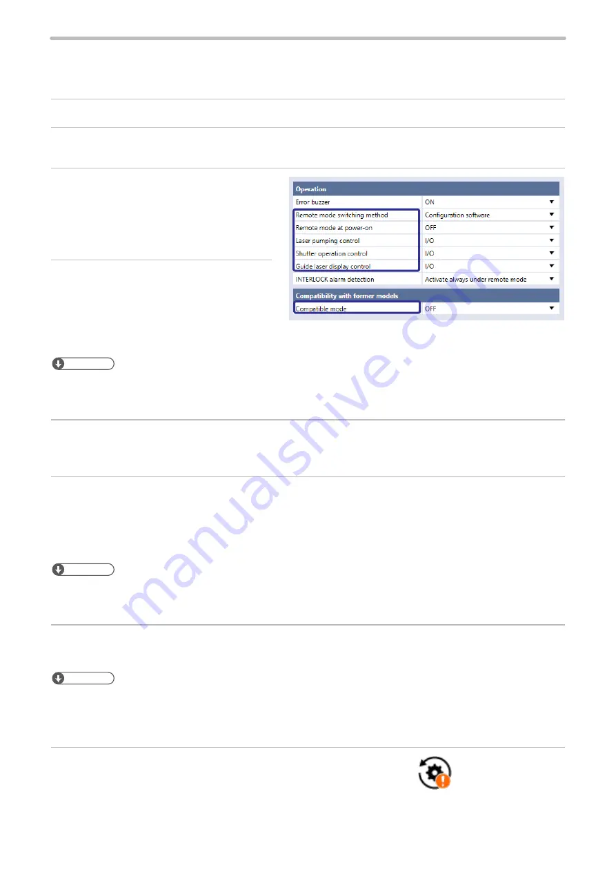
Configure the settings under “Operation” and 
“Compatibility with former models”.

4. 

Select the switching method of the remote 
mode.
•  Configuration software (initial setting)

•  I/O

ンㄆㄇㄆㄓㄆㄏ㄄ㄆ

•  LP-RH/LP-ZV: If “Configuration software” is selected for “Remote mode switching method”, you can switch remote mode 

on and off by Laser Marker NAVI smart and the touch panel console or commercially available monitor. To use the touch 

panel console or monitor, the optional expansion board should be installed on the controller.

5. 

When “Configuration software” is selected, select the remote mode status at power-on.
•  Remote mode ON

•  Remote mode OFF (initial setting)

6. 

Select the control method for the following operations between I/O or communication commands.
As the default, I/O control is selected to all settings.
•  Laser pumping control

•  Shutter operation control

•  Guide laser control


ンㄆㄇㄆㄓㄆㄏ㄄ㄆ

•  To use “Test Marking Command (TST)” and “Laser Radiation for Measurement Command (SPT)” of the communication 

commands, set the shutter operation control method to “communication commands”.

•  If you want to control these I/O operations via optional network unit (EtherNet/IP or PROFINET), select “I/O” here.


7. 

If you use the standard communication commands, set “OFF” to “Compatible mode”. If you want to use the same 
command format with the former models of LP-400/LP-V series, enable “LP-400/V compatibility”.  

ンㄆㄇㄆㄓㄆㄏ㄄ㄆ

•  For the details of the compatible command format with the former models, refer to the “Serial Communication Command 

Guide: LP-400/V compatible mode”.

•  If you use the optional network (EtherNet/IP or PROFINET) for the command control, you cannot use the command 

format of LP-400/V compatible.

8. 

Select “Apply to laser marking system” on the left side of the ribbon.

“Apply to laser marking 

system” tool

ME-LPRH-SM-3

Содержание LP-RH Series

Страница 1: ...024 2 panasonic net id pidsx global ME LPRH SM 3 Please read these instructions carefully before using this product and save this manual for future use Laser Marker Setup Maintenance Guide LP RH serie...

Страница 2: ...y us 5 Please remind that we assume no liability for any results arising out of operations regardless of the above clauses Disclaimer The applications described in this document are all intended for e...

Страница 3: ...uctions to be observed This symbol is used to alert users to a specific operating procedure that must not be performed This symbols is used to alert users to a specific operating procedure that must b...

Страница 4: ...t material which has low reflectivity in case of the radiation of the direct laser beam Do not use the resin or specular objects for a workpiece stand and terminating object Construct an interlock sys...

Страница 5: ...dges of metal parts the protrusions or corners of the product body It may cause injury Install this product in the stable place without vibration and shock In case it falls down it may cause injury Th...

Страница 6: ...lasers are continuously radiated for long periods of time If the laser marker temperature is low laser radiation may not be started Perform test marking and check the marking quality before using the...

Страница 7: ...f the controller and head are at the same electric potential Each connecting cable should not be used in the same raceway or connected in parallel to any device that generates high tension wires power...

Страница 8: ...onnected to a network that includes PCs make sure that the system is not infected by computer viruses or other malicious entities using a regularly updated antivirus program anti spyware program etc U...

Страница 9: ...pecially require the high level of reliability and safety ACCEPTANCE INSPECTION In connection with the Products you have purchased from us or with the Products delivered to your premises please perfor...

Страница 10: ...ompleted machinery 2 EN ISO 11553 1 EN 60204 1 2011 65 EU as amended by EU 2015 863 RoHS Directive EN IEC 63000 Technical specification EN 55032 EN 60825 1 EN Standard UKCA Marking 3 2016 No 1091 Elec...

Страница 11: ...ust collector or an exhauster according to the constituent of such dust or gas Dispose of the exhaust gas safely and appropriately according to the laws and regulations of the country region or area a...

Страница 12: ...utions related to the safety of laser and machines and to implement protective measures for the operations by the user Information for use This document describes information for use on the assumption...

Страница 13: ...wing Laser Marker models In this document this product is called laser marker If the setting contents or specifications vary by models the target models are specified in the text In the text multiple...

Страница 14: ...er Marker NAVI smart This manual describes the procedure and method to operate the laser marker and the screen operations to set marking contents Serial Communication Command Guide This manual describ...

Страница 15: ...ch panel console 33 1 5 Name of Each Component 34 1 5 1 Head 34 1 5 2 Controller 37 2 Laser Marker Installation 42 2 1 Installation Environment 43 2 2 Installation Space 44 2 3 Head Installation 45 2...

Страница 16: ...peration method using external control device 84 3 4 2 Operation procedure with external control 85 3 4 3 General settings before external control 86 3 4 4 Remote mode settings 89 4 External Control U...

Страница 17: ...ANCE OUT 137 5 External Control by Communication Commands 138 5 1 Communication Interfaces 139 5 2 RS 232C 140 5 2 1 Interface specifications and connection 140 5 2 2 Communication settings for comman...

Страница 18: ...ator 186 7 2 6 Galvano scanner 190 7 2 7 Internal shutter 191 7 2 8 Replacement of contactor for interlock 192 7 2 9 Replacement of cable 196 7 3 Obtaining Backup Data 196 7 4 Serial Number Checking M...

Страница 19: ...1 Product Overview ME LPRH SM 3...

Страница 20: ...Tower LP RH101S 55mm x 55mm Standard LP RH101T Tower Model description LP RH 300 S q e w r q Represents the series name LP RH series refers to the CO2 laser marker w Represents the laser output class...

Страница 21: ...ble Optional item Cable to supply AC power to the controller Use the specified optional cable or a cable with the enough rating capacity to fulfil the power voltage specification of this product which...

Страница 22: ...work unit for EtherNet IP LP ANW10 Industrial network unit for PROFINET LP ANW11 Touch panel console LP ADP50 Expansion board 2 LP AEB10 1 Rating 250V AC CE certified cable For Europe plug is complian...

Страница 23: ...use the packing materials to prevent damages during transportation Laser marker head Laser marker head either a standard type or a tower type 1 unit Air filter for replacement for controller Air filte...

Страница 24: ...the I O terminal and one to the I O lines from the I O connector The AC power cable is not included in this product Use the specified optional cable or a cable with the enough rating capacity to fulfi...

Страница 25: ...iles FON Fonts for alphanumeric characters and symbols ORG1 ORG2 ORG3 ORG4 ORG5 ORG1S ORG2S ORG3S OCR1 ORG3 L1 DINLIKE1 L1 Fonts for Japanese characters JIS1 JIS level 1 JIS2 JIS level 2 Fonts for Sim...

Страница 26: ...r specifications Other basic specifications Item Model LP RH300S LP RH300T LP RH200S LP RH200T LP RH100S LP RH100T LP RH301S LP RH301T LP RH101S LP RH101T LP RH305S LP RH305T Marking laser Laser type...

Страница 27: ...2C Ethernet EtherNet IP 8 PROFINET 8 Dedicated software Laser Marker NAVI smart Logo Data Editing Software ExportVec Font Maker Supported OS 9 Windows 11 Pro 64bit Windows 10 Pro 32bit 64bit Laser mar...

Страница 28: ...marker at delivery time with the maximum laser power setting 5 Some of the languages or character types are not supported by this laser marker Characters written from right to left such as Arabic or...

Страница 29: ...nter of marking field e Marking Field X Y LP RH300S LP RH200S LP RH100S 110mm x 110mm LP RH301S LP RH101S 55mm x 55mm LP RH305S 160mm x 160mm r Center of the scanner unit rotation t Screw hole for gen...

Страница 30: ...10mm LP RH301T LP RH101T 55mm x 55mm LP RH305T 160mm x 160mm r Laser pointer emission port Aperture diameter 19mm t Head positioning pin hole of lens side surface 4 0 06 0 02 Depth 6 5 y Head position...

Страница 31: ...380 200 390 161 200 25 29 R100 R100 250 92 92 92 w q q No Description q Controller fixing screw hole 4 holes each on the bottom and left side facing the front M5 screw depth 6 w Screw for protective c...

Страница 32: ...ting 125V AC PSE certified cable For Japan LP ACA10 w Rating 250V AC PSE certified cable For Japan LP ACA11 e Rating 250V AC CE certified cable For Europe LP ACA12 Rating 250V AC CE certified cable Fo...

Страница 33: ...Weight Approx 1 5kg Unit mm 182 265 200 80 0 2 236 0 2 143 0 2 150 0 2 w 54 2900 70 60 36 21 227 15 184 5 e q r No Description q Hook hole for wall hanging hole size 33 mm 5 mm hook part R3 mm Fixing...

Страница 34: ...omponent 1 5 1 Head Standard model LP RH300S LP RH200S LP RH100S LP RH301S LP RH101S LP RH305S 2 3 8 6 7 1 9 10 4 5 Tower head model LP RH300T LP RH200T LP RH100T LP RH301T LP RH101T LP RH305T 3 5 4 2...

Страница 35: ...onnector POWER This is the connector for supplying the power to the head Connect the attached unit power cable For the connecting details refer to 2 6 1 Connection of head and controller P 59 4 Laser...

Страница 36: ...w for Indicating Rotation Angle Only for the standard head This is the arrow that indicates rotation angle of the head scanner For the details refer to 2 3 3 Rotation of Standard Head Scanner P 48 ME...

Страница 37: ...l five seconds or more between ON and OFF Do not turn off the power supply while the system starts while MAIN indicator is flashed on the panel 2 Controller display light Displays the status of the la...

Страница 38: ...ou use a commercially available monitor when operating the laser marker the USB mouse can be connected to this terminal The USB port is also installed to the rear of the controller Do not connect any...

Страница 39: ...aser marker and controls their operations If you want to perform Ethernet communication for the above multiple purposes use an expansion hub 3 RS 232C port RS 232C The port to connect the following ex...

Страница 40: ...ouse to the USB port USB flash drive with security function cannot be used The supported format for USB flash drive are FAT32 or exFAT USB hubs cannot be used 9 VGA connector VGA 2 The connector to co...

Страница 41: ...ntly 15 Clamp The clamp to fix the AC power cable 16 Controller air cooling outlet The air cooling outlet for the controller 1 This port is equipped when the optional network unit EtherNet IP unit PRO...

Страница 42: ...2 Laser Marker Installation ME LPRH SM 3...

Страница 43: ...it Do not use this product at a place with oil mist In case this product is used in a dusty environment take measures to prevent dust from entering into the controller e g using a storage housing When...

Страница 44: ...ead and controller in a well ventilated place respectively Installing near a heating element could cause the ambient temperature exceeding the specification range which may cause malfunction of the pr...

Страница 45: ...gloves Hold the product with both hands Do not hold the cables or connectors at carrying Do not touch the laser emission port on the bottom of the head It may affect the marking quality badly Carry t...

Страница 46: ...g quality and damage the product Clean the laser emission port periodically according to the head installation conditions and environment When fixing the bottom lens side of the tower head model insta...

Страница 47: ...ening torque Standard head Bottom M6 screws at 6 positions 7 mm to 10 mm 3 0N m Tower head Rear 7 mm to 10 mm Bottom laser emission port side 5 mm to 7 mm A B M6 screw Laser marker head A Inserting le...

Страница 48: ...cket head cap screw M4 After rotating the scanner unit fix it tightly The tightening torque shall be 1 5N m Loosen Approx 200 degree Approx 150 degree M4 Hexagon Wrench WARNING Never use the laser mar...

Страница 49: ...sion port 28mm 22mm 28mm 22mm 28mm 22mm y Diameter of laser output range 66mm Standard head model y q w e r t Tower head model t y q w e r Do not place anything in the area between the laser emission...

Страница 50: ...r Use the position where the laser pointer comes closest to the center of the guide laser as a guide for the work distance With the guide laser the following data can be indicated Display mode Descrip...

Страница 51: ...is not closed Use the focus adjusting function when the product is installed Do not use this function for the daily use such as setup change Excessive use of this function may cause failure of the pro...

Страница 52: ...e marking field and spot diameter In addition the amount of the spot diameter difference between the marking field center and the marking field end becomes large which may cause uneven marking quality...

Страница 53: ...ce ambient temperature changes When moving to a place where the ambient temperature is different start using the laser marker only after it gets used to the new temperature environment The following a...

Страница 54: ...e key switch side of the controller down as shown in the figure below For details of installation refer to 1 4 2 Controller P 31 Fix the controller in the following conditions Fixing surface Fixing sc...

Страница 55: ...the installation This may result in injuries electrical shock or failure of the laser marker 1 Turn OFF the key switch of the controller and disconnect the AC power cable 2 Loosen the following screw...

Страница 56: ...the laser marker and tighten the four M3 screws removed earlier into screw holes in four corners of the board Tightening torque 0 5N m Before the work always discharge the static electricity by touch...

Страница 57: ...pansion board is displayed in the System information If the first and second digits of the controller version number are not the same as the first and second digits of the optional expansion board ver...

Страница 58: ...controller and expansion board The software for updating the LP RH LP ZV series Laser Marker Firmware Updater can be downloaded from the following website https www3 panasonic biz ac e fasys software_...

Страница 59: ...ss force to the cable or not to nip the cable at the installation Verify the minimum bend radius of each cable and install them without excess forces being applied q w e Rear of head Rear of controlle...

Страница 60: ...32 Rear of head Power terminal Rear of controller protective conductor terminal Frame ground terminal WARNING Perform the connection of the Power Terminal with power off state Failure to do so may cau...

Страница 61: ...o the terminal 6 Attach the power supply cover Screw size M3 Tightening torque 0 5N m 7 Fix the AC power cable with the clamp Screw size M4 screw Tightening torque 1 0N m 8 Make sure that the cables a...

Страница 62: ...r supply of the laser marker turn ON the switch of the circuit protector with the following procedures 1 Remove causes of the overcurrent 2 Turn OFF the key switch of the controller and disconnect the...

Страница 63: ...ay size 10 6 inch or above Others Pointing device such as a mouse character input device such as a keyboard 1 OS versions of which Microsoft has ended support are excluded The CPU type memory capacity...

Страница 64: ...cted online When grounding the F G of the PC ground it so that it is at the same potential as the F G of this product w Ethernet connection Connect the LAN cable to the Ethernet port on the controller...

Страница 65: ...ker is powered on 2 Connect the console to the console connector CONSOLE on the front of the controller When using the console you need to set it in advance with Laser Marker NAVI smart For details re...

Страница 66: ...n interface device HID class USB mouse When using the monitor and mouse check the operation in advance We do not guarantee the operation of all VGA monitors and USB mouses Do not connect or disconnect...

Страница 67: ...s INTERLOCK terminals it can also be connected to other I O signals such as LASER STOP terminals with the devices t to i depending on the control specifications a Laser radiation warning light To indi...

Страница 68: ...3 Operation Method ME LPRH SM 3...

Страница 69: ...e the laser marker without using the external control devices as PLC Refer to 3 3 6 Test marking and RUN mode P 82 You can edit marking data with Laser Marker NAVI smart even when it is not connected...

Страница 70: ...er indicator of the controller flashes 3 The system startup completes approximately after 10 seconds The MAIN power indicator of the controller changes from blinking light to steady light Do not set t...

Страница 71: ...Be sure to check the file saving before turning off the power 3 Disconnect the online connection Refer to 3 3 4 How to disconnect online connection P 78 Do not turn the laser marker power OFF while be...

Страница 72: ...ted to one PC switch the laser marker connected online using Laser Marker NAVI smart to configure control each laser marker For details of how to operate with the console monitor or mouse refer to the...

Страница 73: ...ing file to the laser marking system Turn off the RUN mode Turn on the RUN mode Input a marking trigger Save the marking file to the laser marking system Select the laser marking system to connect Sel...

Страница 74: ...settings In offline mode at a marking file editing Startup Marking settings Startup screen This screen appears when you start up Laser Marker NAVI smart Select the usage of Laser Marker NAVI smart fr...

Страница 75: ...ete a marking file graphic or font file Acquire the backup of data saved in the laser marker Restore the backup data to the laser marker System settings In this screen you set the system properties of...

Страница 76: ...the Marking settings screen appears Do not remove the USB cable or LAN cable while the online connection with the laser marker is active Do not turn the laser marker power OFF while being connected t...

Страница 77: ...on the left side of the ribbon 4 Select the Connection tool in the ribbon 5 In the Connection dialog select Disconnect The online connection with the laser marking system is now disconnected 6 Turn o...

Страница 78: ...before turning the laser marker power OFF 1 Select the Connection tool in the ribbon or go to the Startup screen and select Online 2 In the Connection dialog select Disconnect The online connection w...

Страница 79: ...d to Administrator The available screens of Laser Marker NAVI smart vary depending on the user role and operating mode Refer to 3 3 2 Screen types P 74 When setting the laser marking system using the...

Страница 80: ...o not delete the password with the remote mode ON 2 Exit the Laser Marker NAVI smart when it is started up 3 Double click and execute ClearPassword exe included in the installation folder Laser Marker...

Страница 81: ...enabled the password will be deleted when connected to online even without executing ClearPassword exe Make sure to uncheck the box next to Clear the password 8 To reconfigure the password start Laser...

Страница 82: ...rking settings screen 2 Select Laser pumping in the ribbon to turn on the laser pumping 3 Click Test marking in the ribbon The Test marking guide laser dialog appears 4 Specify the laser settings such...

Страница 83: ...he ribbon and select RUN ON 4 When you turn ON the RUN mode the laser marker enters into the marking start signal standby state Enter the marking start signal marking trigger in any of the following m...

Страница 84: ...ommunication Guide or PROFINET Communication Guide Control by communication commands remote mode To control the laser marker by communication commands from external devices such as PLC use RS 232C or...

Страница 85: ...rking Control by communication commands I O control OPEN shutter Remote mode ON Select file Confirm READY OUT is ON Trigger Input ON Laser pumping ON It is available to the external control combining...

Страница 86: ...e ON Remote mode OFF initial setting 6 Select the control method for the following operations between I O or communication commands As the default I O control is selected to all settings Laser pumping...

Страница 87: ...ensor which detect the workpiece is in position for lasing Assignment of counter end outputs Assign the counter No to COUNT END A OUT to COUNT END D OUT I O pin No 30 to 33 As the default setting coun...

Страница 88: ...panese and Chinese characters which cannot be specified by the ASCII codes Select Shift JIS for Japanese characters and GB 2312 for simplified Chinese If you use European special characters such as or...

Страница 89: ...need to configure the settings on the system settings screen of Laser Marker NAVI smart in advance If you have configured the laser marker to start up in the remote mode you cannot switch the remote...

Страница 90: ...4 External Control Using I O ME LPRH SM 3...

Страница 91: ...Y10 Y11 Y12 Y13 Y14 Y15 Y16 Y17 Y18 Y19 Y20 Rear of controller I O terminal block I O connector Laser marker Hook The I O terminal block can be removed by holding down the hooks Connector specificatio...

Страница 92: ...ommon 1 Y3 24V OUT Internal power 24V Y4 REMOTE OUT Y5 READY OUT Y6 LASER STANDBY OUT Y7 SYSTEM STANDBY OUT Y8 SHUTTER CLOSE 1 OUT Y9 SHUTTER CLOSE 2 OUT Y10 PROCESSING OUT Y11 PROCESSING END OUT Y12...

Страница 93: ...he common terminal connected internally Make sure to use X1 or Y3 for the internal power 0V OUT X3 and Y1 Do not mix up with the external and internal power supplies Do not connect anything to this wh...

Страница 94: ...in position for lasing According to the ON OFF state of this terminal CHECK OK OUT No 34 or CHECK NG OUT No 35 of I O connector turns on for one shot pulse duration after the trigger processing lasin...

Страница 95: ...e the common terminal connected internally For NPN connection this terminal is connected to the minus side of power which is used for control For PNP connection this terminal is connected to the plus...

Страница 96: ...il of the internal contactor in the controller Connect INTERLOCK and INTERLOCK with the non voltage contact dry contact such as a relay or a switch Do not connect with the voltage contact such as a tr...

Страница 97: ...device and the consumption current for the I O control should be less than 300mA Y4 REMOTE OUT Remote mode output The output is ON during the remote mode Make sure that this terminal is turned ON and...

Страница 98: ...e of the external device laser radiation time and internal processing time of the laser marker Y11 PROCESSING END OUT Trigger processing completed output Output ON when the input marking trigger proce...

Страница 99: ...Short circuited Y18 Y19 OPEN Interlock monitor is switched open and closed with a delay of approx 50ms with reference to each interlock input as shown below 50ms 50ms INTERLOCK INTERLOCK X16 X17 X18...

Страница 100: ...FF Internal Shutter CLOSE Status Alarm E402 Close LASER STOP IN connection and input alarm reset The power supply of laser source is shut down through the internal circuit by the software control Open...

Страница 101: ...N 25 RESERVE System reservation 26 No Name 27 OUT COM 2 Output common 2 28 SET OK OUT 29 DATE GAP OUT 30 COUNT END A OUT 31 COUNT END B OUT 32 COUNT END C OUT 33 COUNT END D OUT 34 CHECK OK OUT 35 CHE...

Страница 102: ...turning ON SET IN is required to control the following operations by I O Select file number Correct the count up count down value of the counter function Reset the count value of the counter function...

Страница 103: ...t binary system by specifying ON OFF of D8 to D15 as shown in the below table D0 to D7 Counter No 0 to 3 16 to 19 Terminal Counter No Input D0 0 OFF D1 1 OFF D2 2 OFF D3 3 ON D4 16 OFF D5 17 OFF D6 18...

Страница 104: ...racter table 2 0 to 15 D12 to D15 Registered character table 3 0 to 15 Registered characters 8 bit 2 D0 to D7 Registered character table 0 0 to 255 D8 to D15 Registered character table 1 0 to 255 Exte...

Страница 105: ...hile this input is turned on the laser marker retains the time and date of the system clock at the point when the input was turned ON then it marks the functional characters for current date expiry da...

Страница 106: ...ck by READY OUT Y5 29 DATE GAP OUT Date gap output This terminal turns ON when the date of the system clock has changed passed the midnight while TIME HOLD IN No 22 is ON This is the output to notify...

Страница 107: ...aking sure that this terminal is turned ON 37 SCRIPTING OUT Scripting output This is the terminal you will use when the link control function with the image checker is configured This terminal turns O...

Страница 108: ...ON until the one shot output time ends 1 Use PROCESSING END OUT Y11 and PROCESSING FAIL OUT Y12 for the confirmation of marking completion 1 Set the output time of the one shot output on the system s...

Страница 109: ...wer supply 24V DC External power supply 24V DC NPN open collector output PNP open collector output Each input Each input This product supports both the NPN transistor output and the PNP transistor out...

Страница 110: ...t Load Load Each output This product supports both the NPN transistor output and the PNP transistor output However the wiring from I O terminal block and the I O connector respectively cannot be used...

Страница 111: ...voltage contact dry contact such as a relay or a switch Do not connect with the voltage contact such as a transistor Pin X16 INTERLOCK 1 Pin X17 INTERLOCK 1 Pin X18 INTERLOCK 2 Pin X19 INTERLOCK 2 Pi...

Страница 112: ...13 Y14 Y15 Y16 Y17 Y18 Y19 Y20 I O terminal block REMOTE INTERLOCK IN Short circuited Short circuited Short circuited Short circuited Short circuited Do not short circuit 24V OUT X1 Y3 and 0V OUT X3 Y...

Страница 113: ...ect anything to the internal power 24V OUT X1 Y3 or 0V OUT X3 Y1 of the I O terminal block If a jumper wire is installed remove it IN COM 1 and OUT COM 1 of the I O terminal block are independent from...

Страница 114: ...17 INTERLOCK 2 X18 INTERLOCK 2 X19 REMOTE INTERLOCK X20 OUT COM 1 X12 INTERLOCK 1 MONITOR INTERLOCK 1 MONITOR COM INTERLOCK 2 MONITOR INTERLOCK 2 MONITOR COM INTERLOCK 1 INTERLOCK 1 INTERLOCK 2 REMOTE...

Страница 115: ...er Open the I O monitor with the following procedure 1 Establish an online connection between your PC and the laser marking system 2 Go to the Monitor screen 3 Select I O monitor in the ribbon The I O...

Страница 116: ...2 Go to the Maintenance screen 3 Select Output simulation in the ribbon 4 Output simulation dialog appears Click the output terminal name to simulate then the output status of the laser marker changes...

Страница 117: ...N OFF ON OFF ON OFF ON OFF ON OFF ON OFF ON OFF ON OFF ON OFF ON OFF Open Close ON OFF Close Open ON OFF Normal Error ON OFF Normal Error REMOTE IN X4 1 LASER SUPPLY IN X6 SHUTTER ENABLE IN X9 SHUTTER...

Страница 118: ...In the laser pumping completed state Total time for shutter opening T3 and marking data creation It varies depending on the quantity of the setting data When the laser pumping is not completed Total t...

Страница 119: ...0ms to max 1 second from turning ON OFF of SHUTTER IN X8 to turning ON OFF of SHUTTER CLOSE 1 OUT Y8 and SHUTTER CLOSE 2 OUT Y9 Note that the shutter does not open until the laser pumping is completed...

Страница 120: ...igger delay time marking preparation time laser radiation time and processing time after marking has completed T3 0 to 9999ms When the trigger delay time is set in the selected file trigger processing...

Страница 121: ...arks T1 2 ms or more Keep the ON status for the duration of repeating the lasing operation T2 0 to 9999 ms When the trigger delay time is set in the selected file trigger processing lasing operation s...

Страница 122: ...arts after a lapse of the setting period T4 2 to 510 ms This is the output to notify that the marking trigger processing completed normally This is One shot output Set the output time on the system se...

Страница 123: ...e preset marking position T4 2 to 510ms This is the output to notify that the marking trigger processing completed normally This is One shot output Set the output time on System settings screen There...

Страница 124: ...X5 is turned on till when the workpiece comes to the preset marking position T3 Time it takes the workpiece to move to the setting intervals mm T4 2 to 510ms This is the output to notify that the mark...

Страница 125: ...the input interval of TRIGGER IN If this interval is too short warning E618 occurs and subsequent marking will be canceled T5 2 to 510ms This is the output to notify that the marking trigger processi...

Страница 126: ...arking data creation It varies depending on the quantity of the setting data T3 Max 10 sec If ENCODER B IN X14 does not turn on within 10 seconds from turning on of ENCODER A IN X13 time out error E60...

Страница 127: ...workpiece could not be detected PROCESSING END OUT Y11 turns on unless the trigger processing operation is interrupted This is One shot output Set the output time on System settings screen There is a...

Страница 128: ...rom start up 1 Select the indication contents of the guide laser with SELECT 0 IN to SELECT 2 IN as follows Radiation details SELECT 0 IN No 19 SELECT 1 IN No 20 SELECT 2 IN No 21 Work distance OFF OF...

Страница 129: ...margin of error for the setting value T4 In the laser pumping completed and shutter opened state Time for marking data creation It varies depending on the quantity of the setting data When the laser...

Страница 130: ...ed regardless of the file number remote mode ON OFF status or error status If you turn on off TIME HOLD IN No 22 continuously keep the OFF time at least for two seconds 4 6 13 Counter end output T1 T1...

Страница 131: ...the ON status for 2ms or more 1 Select the number input target with SELECT 0 IN to SELECT 2 IN as follows Number input target SELECT 0 IN No 19 SELECT 1 IN No 20 SELECT 2 IN No 21 Count up value corre...

Страница 132: ...28 turns on T5 0 5ms or more After a lapse of 0 5ms or more from specifying SELECT 0 IN to SELECT 2 IN and D0 IN to D15 IN turn on SET IN No 2 1 To reset the counter set SELECT 0 IN to SELECT 2 IN as...

Страница 133: ...mpiling has finished within the trigger processing time 1ms or less When the next marking data compiling did not finish within the trigger processing time The remaining time of the marking data compil...

Страница 134: ...m turning ON OFF of SHUTTER IN X8 to turning ON OFF of SHUTTER CLOSE 1 OUT Y8 and SHUTTER CLOSE 2 OUT Y9 SHUTTER CLOSE 1 OUT and SHUTTER CLOSE 2 OUT will be output by the same operation but their outp...

Страница 135: ...Item Time Remarks T1 Max 1 sec There is a delay time of around 200ms to max 1 second from turning ON OFF of SHUTTER IN X8 to turning ON OFF of SHUTTER CLOSE 1 OUT Y8 and SHUTTER CLOSE 2 OUT Y9 T2 100m...

Страница 136: ...arks T1 Approx 50ms INTERLOCK MONITOR is switched open and closed with a delay of approx 50ms with reference to each INTERLOCK input T2 Max 1 sec There is a delay time of around 200ms to max 1 second...

Страница 137: ...1 sec from the instant when the operating time or the number of operations of a part subject to maintenance reaches the maintenance criterion to the instant when MAINTENACE OUT Y13 turns ON T2 Max 10...

Страница 138: ...5 External Control by Communication Commands ME LPRH SM 3...

Страница 139: ...on software External device for communication command control PLC and PC for control Specific image checker e Ports for industrial network EtherNet IP or PROFINET Available when the optional network u...

Страница 140: ...r to Serial Communication Command Guide 5 2 1 Interface specifications and connection To execute command communication control with RS 232C connect the RS 232C port on the controller to the external c...

Страница 141: ...g to PLC a type of the cable straight or cross differs depending on a manufacturer or a model Please follow the PLC manual To connect RS 232C terminal without using a commercially available RS 232C ca...

Страница 142: ...X can be specified Initial setting of positive response code A Initial setting of negative response code E Initial setting of read request response code A Character code ASCII code Encoding for non AS...

Страница 143: ...a HUB or a router PC configuration software External device for communication command control PLC and PC for control Specific image checker Orange LED Green LED RJ 45 8 pole connector AUTO MDIX compa...

Страница 144: ...nding on the combination For the details of the communication settings refer to 3 4 3 General settings before external control P 86 Ethernet communication settings for communication command control It...

Страница 145: ...PC etc HUB or rooter Laser marker controller Several units connected Example of communication system settings Set a separate IP address not to overlap between the laser marker and PC on the network PC...

Страница 146: ...connection between your PC and the laser marking system 2 Go to the Maintenance screen 3 Select Command history tab Up to 100 command messages received or sent by the laser marker are shown in the lis...

Страница 147: ...6 Link Control with External Devices ME LPRH SM 3...

Страница 148: ...he marked code symbols or characters The readout data and marking data are collated by the image checker and the checkup result is output from the laser marker Marking Image checking image capturing a...

Страница 149: ...on information to the laser marker Image checker Output the consistent OK inconsistent NG results transmitted by the code reader I O connector Laser marker Correct the marking position Perform marking...

Страница 150: ...pumping ON Shutter open Start the image checker and laser marker Start up and online connect the Laser Marker NAVI smart Laser marker marking trigger input Check the marking trigger ready output ON T...

Страница 151: ...cations and connection of the Ethernet port refer to 5 3 Ethernet P 143 Connection example To connect a position correction device PV230 code reader DataMan and control PLC with the laser marker PLC F...

Страница 152: ...Address For image checking after marking Model of image checker PV230 PV200 DataMan IP Address Port for DataMan Specify these values according to communication settings of the image checker to connec...

Страница 153: ...ter marking Model PV230 PV200 DataMan Application Code checking Character checking Image capturing and inspection The application of the image checking before marking is fixed to Marking position corr...

Страница 154: ...pe specified here is consistent with the image checker PV230 PV200 setting When the application is set to code checking and if you want to check the code symbol and human readable text at the same tim...

Страница 155: ...IN signal input TIMING IN signal within 60 seconds after completion of the initial operation For input of TIMING IN signal refer to 6 1 8 Timing chart P 161 Input TIMING IN signal by I O control Any c...

Страница 156: ...the link control function with the laser marker and PV230 PV200 configure the system settings on the PV230 PV200 as follows 1 From Environment Input Output setting screen of PV230 PV200 select the Ge...

Страница 157: ...the coordinates in the order of X Y theta in the expression table that you want to send to the laser marker for the positional correction Then set Yes to Output of each expression The results of the...

Страница 158: ...ion of PV230 so that you can read the marking codes without problem 5 Select Judgement Limits of the checker and set Yes to the String Judgement You do not have to input Judgement Characters The marki...

Страница 159: ...at are not supported by PV230 Up to 80 characters can be checked with one checker 5 Select Inspection Judgement and set JDC External to Type 6 Set the results of the one or more checkers in the expres...

Страница 160: ...ecifications and setting of code reader DataMan refer to the instruction manual for DataMan Ensure that any code other than the readout target is in the DataMan shooting range Code reading is not perf...

Страница 161: ...detection by image checker Time for marking position correction by the laser marker T3 When TRIGGER IN X5 is accepted PROCESSING OUT Y10 turns ON The output time of PROCESSING OUT includes the trigger...

Страница 162: ...arker internal processing time of the linkage devices T3 Laser radiation time This varies depending on marking contents T4 Processing time of communication and linkage operations with the image checke...

Страница 163: ...ESSING OUT Y10 turns ON The output time of PROCESSING OUT includes the trigger delay time operation time laser radiation time and laser marker internal processing time of the linkage devices T4 Max 60...

Страница 164: ...ESSING OUT includes the trigger delay time operation time laser radiation time and laser marker internal processing time of the linkage devices T3 Processing time of linkage operations with the image...

Страница 165: ...bar code 2D code is set for the specified object number change the input characters of the code to mark 6 2 1 Example of code reader linkage system ABCD e w q q Use a commercially available code reade...

Страница 166: ...the file number or name Marking trigger input Laser radiation Start up and online connect the Laser Marker NAVI smart Laser pumping ON RUN mode ON Shutter open automatic Remote mode ON Laser pumping...

Страница 167: ...mart Marking target file selection Laser pumping ON RUN mode ON Shutter open automatic Remote mode ON Select File Laser pumping ON Shutter open Repeat this procedure During remote mode control During...

Страница 168: ...er Use the RS 232C cross cable to connect the code reader and laser marker referring to the example below Connection example TxD RxD GND 2 3 5 TxD RxD GND 2 3 5 2 3 5 2 3 5 D sub 9 pin female Laser ma...

Страница 169: ...e performance and operation before use To connect the RS 232C port with the code reader the communication command control by RS 232C is disabled The control is enabled only when the laser marker is in...

Страница 170: ...tion settings of the code reader to connect Set Code reader to the RS 232C usage For the code reader linkage function the following items of communication settings are fixed values Align the code read...

Страница 171: ...ommunication checksum is transferred to the laser marker as marking data The end code CR is not subject to the data extraction 7 If the control contents are set to character data transmission specify...

Страница 172: ...7 Maintenance ME LPRH SM 3...

Страница 173: ...ssion port f lens Contamination Cleaning By our service representatives w Galvano scanner Aging By our service representatives e Internal shutter Aging By our service representatives r Air filter Cont...

Страница 174: ...n in quality of marking and processing density reduction of the marking incomplete processing is observed There is contamination or scratch that cannot be removed by cleaning Replacement method Replac...

Страница 175: ...hanol to wipe it Do not wipe the laser emission port strongly or touch it with a sharp pointed object Laser marker might become faulty WARNING Never use an inflammable air duster The laser beam may ig...

Страница 176: ...urn OFF the key switch of the controller and disconnect the AC power cable 2 Vacuum the intake exhaust vent and remove the dust q q w w Head q w Controller q Intake w Exhaust Do not blow air to the in...

Страница 177: ...ce screen of Laser Marker NAVI smart 1 Establish an online connection between your PC and the laser marking system Go to the Maintenance screen Operating data tab 2 Check the setting of the Air filter...

Страница 178: ...dried cloth Do not blow air to the intake exhaust vent If the dust penetrates in the laser marker it may result in failure 5 Mount a new filter on the panel Set the filter side with the convex shape a...

Страница 179: ...ntenance history update the maintenance information with the Laser Marker NAVI smart Go to the Runtime data tabs on the Maintenance screen in the Laser Marker NAVI smart and select Done on Air filter...

Страница 180: ...filter cover Loosen the two M3 screws on the front and remove the cover 3 If the cover is contaminated remove the dust with a vacuum cleaner or a dried cloth 4 Remove the filter 5 If the intake vent i...

Страница 181: ...The filter has upper and lower halves that are the same in size and shape 7 Attach the filter cover Insert the lower part of the cover to the controller and tighten the upper screw 2 positions Screw...

Страница 182: ...ontamination on the fan that cannot be removed by cleaning Abnormal noise is generated from the fan The fun slowdown warning is occurring Replacement method Air cooling fan for head Our service repres...

Страница 183: ...e fan guard and the fan itself from the controller WARNING Do not drop the fan mounting nut inside the controller It may short circuit the internal circuits and cause accident or malfunction 5 Remove...

Страница 184: ...rker Install the controller fans in the direction so that the air flow matches the intake direction Fan installed in the wrong way causes the flow to go in the wrong way which may failure of the produ...

Страница 185: ...e get caught while installing the air filter 10 Install the front cover of the controller 11 If you replaced the fans to new one reset the operating information in Laser Marker NAVI smart Go to the Ma...

Страница 186: ...sity reduction of the marking incomplete processing is observed Setting a large value for the laser power is not reflected in the quality of marking and processing The laser power measured with a comm...

Страница 187: ...ntaminated or damaged an error may result in the measurement of the laser power 2 Install the power meter Put the detector of the laser power meter vertically down from the center of the laser emissio...

Страница 188: ...n dialog to irradiate the laser Use the guide laser to confirm the setting position of the power meter detector Place the detector so that the cross indication is on the center of the detector For sta...

Страница 189: ...default setting correct the laser power setting value in the System settings screen System offset Setting range of laser power correction 50 to 200 Laser power correction refers to the function to co...

Страница 190: ...rking frequency and conditions If uneven wear develops accurate reproducing may become difficult resulting in skewness or misalignment of marking lines Replacement interval Deterioration in quality of...

Страница 191: ...rval Total number of opening closing operations has exceeded two million Alarm for internal shutter error occurred If the number of shutter cycles has exceeded two million the symbol is displayed on t...

Страница 192: ...MONITOR terminals Y16 Y17 Y18 Y19 does not correspond to the input status of INTERLOCK terminals X16 X17 X18 X19 Alarm for INTERLOCK open E400 E401 cannot be released If the number of switching cycles...

Страница 193: ...top Two M3 screws on the side Contactor 3 Disconnect the two connectors of the contactor Before the maintenance work always discharge the static electricity by touching the grounded metal objects etc...

Страница 194: ...he cable get caught while installing To the optional contactor unit the cables are already connected at the delivery state 7 Connect the two connectors of the contactor to the controller 8 Connect the...

Страница 195: ...ctor reset the operating data in Laser Marker NAVI smart Go to the Maintenance screen and select Operating data For Number of switching cycles of INTERLOCK contactors select Reset and confirm with Yes...

Страница 196: ...ining Backup Data Obtain and keep a backup of data registered in the laser marker periodically using the Laser Marker NAVI smart in case of replacing laser markers for repairing and maintaining purpos...

Страница 197: ...mber of the laser marker is written on the area marked by a circle in the figure below Rear of standard head Side of standard head Rear of controller Check it on Laser Marker NAVI smart 1 Establish an...

Страница 198: ...unction expansion board is installed make sure that no external storage medium such as a USB flash drive is connected to the USB ports on the controller 1 position on the front and 2 positions on the...

Страница 199: ...gislation By disposing of them correctly you will help to save valuable resources and prevent any potential negative effects on human health and the environment For more information about collection a...

Страница 200: ...oller and disconnect the AC power cable 2 Loosen the following screws and remove the side panel of the controller Five M3 screws on the back One M3 screw on the top Two M3 screws on the side 3 Cut the...

Страница 201: ...Troubleshooting ME LPRH SM 3...

Страница 202: ...rotector is OFF Turn on the circuit protector by following the procedures described in the Setup Maintenance Guide Laser pumping Troubles Causes Measures Laser pumping does not start The connection of...

Страница 203: ...not installed properly Refer to the Laser Marker NAVI smart Operation Manual to install the USB driver to all the laser markers to connect Online connection is disconnected PC is in the sleep or hibe...

Страница 204: ...ble the Bluetooth communication in the system settings Then restart the laser marker PC s Bluetooth module is apart from the head of the laser marker Operate the product with the laser marker head wit...

Страница 205: ...ck if the detecting position of the workpiece surface and the marking surface are consistent For LP GS LP ZV series The set Z position does not match the height of the actual target object The LP GSxx...

Страница 206: ...than 2ms per marking cycle The marking trigger is entered while the marking trigger ready is OFF Refer to External Control in Troubleshooting Sometimes laser is emitted unintentionally Fumes causes m...

Страница 207: ...on according to the workpiece height For LP ZV series when you use the autofocus function The workpiece displacement does not match the actual distance Check if the input values of Workpiece displacem...

Страница 208: ...ic workpieces the pulse duration 4ns or 8ns is a common setting and for metal 16ns or 30ns is often selected For the shallow marking of the metal surface the pulse duration 120ns or 200ns is often sel...

Страница 209: ...n if workpiece is in full stop Turn the marking trigger signal ON after vibrations are completely damped Disturbed at the end of marking Workpiece is likely to start moving before completion of markin...

Страница 210: ...GS LP RC LP RH series Setting of laser frequency and scan speed is inadequate Decrease scan speed or increase laser frequency For LP RF LP RV LP ZV series Setting of pulse cycle and scan speed is inad...

Страница 211: ...ing of the moving direction is wrong Match feed direction with laser marker operation Check the setting direction of the laser head of the system settings screen Speed changes at conveyor junction If...

Страница 212: ...character spacing is too wide Increase the setting When the character spacing is too narrow Decrease the setting In some cases it may reduce the influence of the ups and downs of the line speed to dec...

Страница 213: ...ged at the time of backup file restoration Check the communication setting If Ethernet or EtherNet IP is used check the IP address etc When the backup file is restored the communication setting is ove...

Страница 214: ...t IP or PROFINET Marking trigger ready does not turn ON An error occurs Check the error code and cancel the alarm or warning Marking trigger is in progress Do not input the next marking trigger until...

Страница 215: ...sponse is returned The requested operation can be controlled only by I O with the current system settings To use the following commands specify the control method to the communication command in Laser...

Страница 216: ...want to use the same command format with the former models of LP 400 LP V series or LP M LP S LP Z series set Compatible mode in system settings of Laser Marker NAVI smart If you want to use the stan...

Страница 217: ...nication Calibration Settings of the positional correction Expression of the numeric calculation The setting order of the expression table of PV230 PV200 is inadequate The results of the numerical cal...

Страница 218: ...and marking start end timing are inadequate when TIMING IN signal is used the vibration affects marking Turn TIMING IN signal ON after workpiece is fully stopped To feed works after marking check tha...

Страница 219: ...Mouse does not respond The mouse is connected to the USB hub Connect the USB mouse to the laser marker controller directly without USB hub The mouse type is not supported by the laser marker Use the U...

Страница 220: ...e any of the following means to input the alarm reset Click the confirmation button in the error dialog on the configuration software Laser Marker NAVI smart screen Turn ON ALARM RESET IN X15 on the I...

Страница 221: ...xhaust port and fan located at the air cooling area of the controller If the air filter is contaminated replace it Replace the fan E220 Laser head housing is open Contact our sales office or represent...

Страница 222: ...5 An error has occurred to the Z axis adjustment module Check the connection of the cable and various signal lines and then restart the laser marker E400 INTERLOCK 1 of the I O terminal block was rel...

Страница 223: ...r input control Check wiring of I O or communication port to the external control devices Check the switch or the sensor connected to TRIGGER IN of I O terminal operates properly without chattering E4...

Страница 224: ...saving data Unable to read the file data Overwrite the data again to the selected file number Do not turn off the laser marker while saving the settings E530 E542 E571 Restore the backup file saved be...

Страница 225: ...escription Measures 1 E600 LASER STOP IN of the I O terminal block was released Connect the LASER STOP IN terminals of the I O terminal block Check the status of the safety equipment connected to the...

Страница 226: ...the setting values E614 E615 2 5 E651 2 5 Existed marking data with its Z position outside of marking field The LP GSxxx L type is excluded Adjust the Z movement of the object group settings Adjust t...

Страница 227: ...the laser marker Trigger processing terminated abnormally Check the connection of the cable and various signal lines and then restart the laser marker E622 I O connector TIMING IN was not input withi...

Страница 228: ...ading failed when the code reading function is used for the link control with external devices Check the status of external devices Improve the marking quality of the code To send the marking strings...

Страница 229: ...to the font No specified Register the font file on the data management screen Using the character conditions specify the font No in which the font file is registered E655 Insufficient font memory Fon...

Страница 230: ...RGET DETECTION IN For LP ZV series Autofocus function and continuous trigger of trigger mode For LP ZV series 3D marking and external offset with I O For LP ZV series when the 3D marking is ON the bar...

Страница 231: ...de type E674 The string containing is not properly set If the functional characters such as a counter and date time are input delete and re enter characters after To enter as a character to mark enter...

Страница 232: ...nd points in the same position E687 The graphic object contains an invalid setting Reduce the graphic size The graphic width or height should be less than 999 999 mm If the Graphic presets is off set...

Страница 233: ...ves E710 E711 2 3 The head air cooling fan has stopped Refer to Setup Maintenance Guide and clean the fan Check the connection status of the fan connector Replace the fan For LP RC series confirm the...

Страница 234: ...N turned ON until SET OK OUT turns ON To input the No input again close the shutter and reset the previous data Check the connection with the external controller Check the control procedure of the ext...

Страница 235: ...ker used and perform updating If the GSD file version is incorrect settings by your PLC cannot be imported to the laser marking system correctly E783 5 6 The version of the expansion board is incorrec...

Страница 236: ...Index ME LPRH SM 3...

Страница 237: ...r emission port 174 Laser Marker NAVI smart 63 Laser Marker Smart Utility 21 Laser oscillator 186 Laser Pointer Emission Port 35 Laser stop 114 134 Link Control with Code Reader 165 Link Control with...

Страница 238: ...238 Test marking 69 82 TIMING IN 155 U Unit power cable 32 USB 38 39 64 W Warning 225 ME LPRH SM 3...

Страница 239: ......

Страница 240: ...sonic Industrial Devices SUNX Co Ltd 2023 2024 February 2024 Panasonic Industrial Devices SUNX Co Ltd https panasonic net id pidsx global Please visit our website for inquiries and about our sales net...

Отзывы: