


567
CHAPTER 12 CONTROL SUB FUNCTIONS
12
12.
6 Abs
olut
e Pos
ition
Res
tora
tion
F
unc
tion
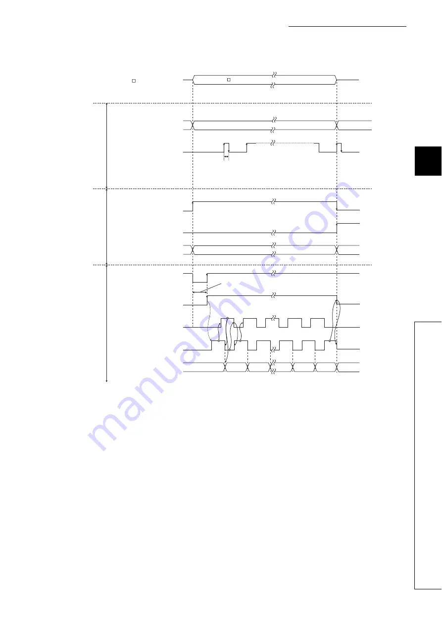
• The following drawing shows an operation when data is transferred to the servo amplifier.
1.
The BUSY signal is turned ON and the axis operation status is set to "Analyzing" by the dedicated
instruction "ABRST
". At this time, the signal is controlled to turn OFF the servo amplifier. The
servo is powered OFF in 60ms + scan time.
2.
When the servo is turned ON, the ABS transfer mode is simultaneously turned ON. After receiving
the ABS transfer mode, detecting the absolute position and calculating the absolute position, the
servo amplifier will turn ON the ABS transmission data ready (ABST) and answer back to LD75
notifying that the send data is ready.
3.
After recognizing that the ABS transmission data ready (ABST) turned ON, LD75 turns ON the ABS
request (ABSR).
4.
The servo amplifier outputs the ABS lower 2 bits and ABS transmission data ready (ABST) OFF by
the ABS request (ABSR).
5.
After recognizing that the ABS transmission data ready (ABST) turned OFF (the ABS2bit data is
output), LD75 reads the lower 2bits of ABS and turns OFF the ABS request (ABSR).
2.
3.
5.
4. 6.
7.
1.
ABRST
S+4 (Status)
D+0 (Complete device)
ON
OFF
ON
OFF
ON
OFF
ON
OFF
ON
OFF
ON
OFF
Positioning complete
signal
BUSY signal
Axis operation status
Servo ON
(SON)
ABS transfer
mode (ABSM)
ABS request (ABSR)
ABS transmission
data ready (ABST)
Transmission (ABS) data
Statuses of
devices
Statuses of
the LD75
I/O signals
from/to servo
amplifier
"ABRST " is executed continuously until "S+4" becomes 0.
ON for one scan
0
0
Analyzing
ABS transmitting
Lower
2bit
Checksum
higher 2bit
Standby
Values other than 0 (the phase numbers of absolute position restoration) is
stored after the process starts.
Approx. 60ms + scan time
Содержание MELSEC-L LD75D
Страница 1: ...MELSEC L LD75P LD75D Positioning Module User s Manual LD75P1 LD75P2 LD75P4 LD75D1 LD75D2 LD75D4 ...
Страница 2: ......
Страница 11: ...9 Memo ...
Страница 47: ...45 CHAPTER 2 SYSTEM CONFIGURATION 2 2 1 General Image of System 1 When connected to a CPU module ...
Страница 176: ...174 ...
Страница 264: ...262 ...
Страница 266: ...264 ...
Страница 267: ...265 CHAPTER 6 PROGRAM USED FOR POSITIONING CONTROL 6 6 4 Positioning Program Examples ...
Страница 268: ...266 ...
Страница 269: ...267 CHAPTER 6 PROGRAM USED FOR POSITIONING CONTROL 6 6 4 Positioning Program Examples ...
Страница 270: ...268 ...
Страница 271: ...269 CHAPTER 6 PROGRAM USED FOR POSITIONING CONTROL 6 6 4 Positioning Program Examples ...
Страница 272: ...270 Z ABRST1 instruction execution ...
Страница 273: ...271 CHAPTER 6 PROGRAM USED FOR POSITIONING CONTROL 6 6 4 Positioning Program Examples ...
Страница 278: ...276 ...
Страница 279: ...277 CHAPTER 6 PROGRAM USED FOR POSITIONING CONTROL 6 6 4 Positioning Program Examples ...
Страница 280: ...278 ...
Страница 281: ...279 CHAPTER 6 PROGRAM USED FOR POSITIONING CONTROL 6 6 4 Positioning Program Examples ...
Страница 282: ...280 ...
Страница 283: ...281 CHAPTER 6 PROGRAM USED FOR POSITIONING CONTROL 6 6 4 Positioning Program Examples ...
Страница 284: ...282 ...
Страница 285: ...283 CHAPTER 6 PROGRAM USED FOR POSITIONING CONTROL 6 6 4 Positioning Program Examples ...
Страница 286: ...284 ...
Страница 287: ...285 CHAPTER 6 PROGRAM USED FOR POSITIONING CONTROL 6 6 4 Positioning Program Examples ...
Страница 316: ...314 Memo ...
Страница 685: ...683 APPENDICES A Appendix 1 Function Update Appendix 1 1 Function comparison Memo ...
Страница 738: ...736 Memo ...
Страница 806: ...804 5 LD75D2 Unit mm 6 LD75D4 Unit mm 45 4 90 4 95 4 45 45 DIN rail center 45 4 90 4 95 4 45 45 DIN rail center ...
Страница 817: ......


