


ML62Q1000 Series User's Manual
Chapter 9 Functional Timer (FTM)
FEUL62Q1000
9-37
9.3 Description of Operation
Four types of operation modes are available for the functional timer:
•
TIMER mode
•
CAPTURE mode
•
PWM1 mode
•
PWM2 mode
9.3.1 Common Sequence (Initial setting Common to All Modes)
FTMn starts operating through the FTCSTR register after the setting via steps 1 through 6 described below is performed.
During operation, the hardware states such as interrupt status can be checked and the cycle/event settings are updateable.
1: Mode setting (FTnMOD register)
Choose the TIMER/CAPTURE/PWMs mode using the FTnMOD register.
In addition, set the repeat mode/one-shot mode.
2: Clock setting (FTnCLK register)
Choose the timer clock and the count clock.
If the internal clock is chosen for the count clock, the frequency dividing ratio can also be set.
3: Trigger setting (FTnTRG0 register, FTnTRG1 register)
Use this setting when starting/stopping the counter by an event trigger.
In the FTnTRG0 register, choose the event trigger source and the action. In the FTnTRG1 register, choose the edge of
the event trigger/emergency stop.
4: Interrupt setting (FTnINTE register)
Set the interrupt source.
Choose from cycle/event (counter coincidence, duty, capture) and trigger start/stop interrupt.
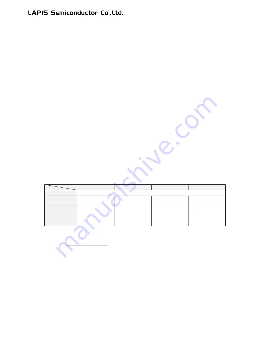
5: Cycle/event setting (FTnP register, FTnEA register, FTnEB register, FTnDT register)
Set the cycle, data for counter coincidence, duty, and dead time, etc.
TIMER mode
CAPTURE mode
PWM1 mode
PWM2 mode
FTnP register
Cycle in repeat mode or timeout period in one-shot mode
FTnEA register
Coincident interrupt
setting value
(Capturing data)
Positive phase
output duty
Duty
FTnEB register
Coincident interrupt
setting value
Negative phase
output duty
(Unused)
FTnDT register
Dead time for output
(Unused)
Dead time for
output
Dead time for
output
The cycle is calculated as follows:
T
priod
=
FTnP + 1
(FTnP: 0x0001 to 0xFFFF)
Counting clock [Hz]
Содержание ML62Q1000 Series
Страница 17: ...Chapter 1 Overview...
Страница 112: ...Chapter 2 CPU and Memory Space...
Страница 154: ...Chapter 3 Reset Function...
Страница 166: ...Chapter 4 Power Management...
Страница 196: ...Chapter 5 Interrupts...
Страница 248: ...Chapter 6 Clock generation Circuit...
Страница 274: ...Chapter 7 Low Speed Time Base Counter...
Страница 291: ...Chapter 8 16 Bit Timer...
Страница 320: ...Chapter 9 Functional Timer FTM...
Страница 382: ...Chapter 10 Watchdog Timer...
Страница 402: ...Chapter 11 Serial Communication Unit...
Страница 456: ...Chapter 12 I2 C Bus Unit...
Страница 491: ...Chapter 13 I2 C Master...
Страница 512: ...Chapter 14 DMA Controller...
Страница 531: ...Chapter 15 Buzzer...
Страница 550: ...Chapter 16 Simplified RTC...
Страница 559: ...Chapter 17 GPIO...
Страница 594: ...Chapter 18 External Interrupt Function...
Страница 612: ...Chapter 19 CRC Generator...
Страница 632: ...Chapter 20 Analog Comparator...
Страница 644: ...Chapter 21 D A Converter...
Страница 655: ...Chapter 22 Voltage Level Supervisor...
Страница 676: ...Chapter 23 Successive Approximation Type A D Converter...
Страница 709: ...Chapter 24 Regulator...
Страница 714: ...Chapter 25 Flash Memory...
Страница 743: ...Chapter 26 Code Option...
Страница 750: ...Chapter 27 LCD Driver...
Страница 788: ...Chapter 28 On Chip Debug Function...
Страница 795: ...Chapter 29 Safety Function...
Страница 813: ...Appendix A...
Страница 881: ...Revision History...