


ML62Q1000 Series User's Manual
Chapter 4 Power Management
FEUL62Q1000
4-27
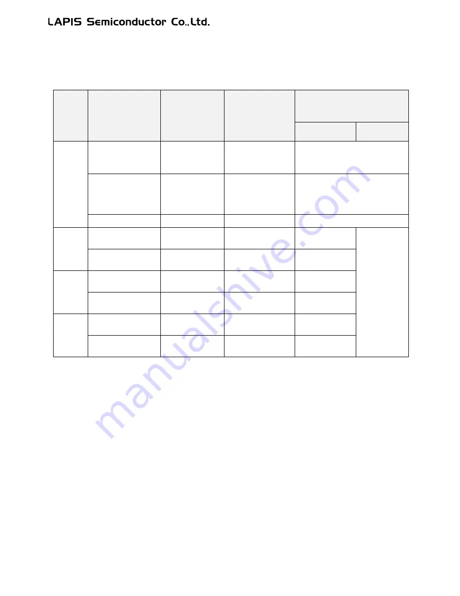
Table 4-5 shows the wake-up time (restoring time) from the standby modes.
See Chapter 6 "Clock Generation Circuit" for details of the FHWUPT register.
Table 4-5 Wake-up Time from Standby Mode
Function
Condition
CPU clock
restoring time
[T
RTCPU
]
Low-speed clock
restoring time
(Low-speed RC
oscillation)
[T
RTLS
]
High-speed clock restoring time (PLL
oscillation)
[T
RTPLL
]
FHWUPT=0x01
FHWUPT=0x00
HALT
mode
Low-speed CPU clock
High-speed clock OFF
No CRC calculation
Approximately
150
μs
Operation continued
Stopped
Low-speed CPU clock
High-speed clock ON
or with CRC
calculation
Approximately
60
μs
Operation continued
Operation continued
High-speed CPU clock
-
Operation continued
Operation continued
HALT-H
mode
No CRC calculation
T
RTPLL
+ 90
μs
Operation continued
Approximately
60
μs
Approx. 2.5 ms
With CRC calculation
T
RTPLL
Operation continued
Approximately
60
μs
STOP
mode
Low-speed CPU clock
T
RTLS
Approximately 320
μs
Approximately
305 μs
High-speed CPU clock
T
RTPLL
Approximately 320 μs
Approximately
305 μs
STOP-D
mode
Low-speed CPU clock
T
RTLS
Approximately 320 μs
Approximately
305 μs
High-speed CPU clock
T
RTPLL
Approximately 320 μs
Approximately
305 μs
[Note]
Ÿ
If SYSTEMCLK is switched to high-speed after the STOP/STOP-D mode is released and before the
high-speed clock wake-up time passes, the CPU must wait to run the program because the clock supply
is suspended until the end of the wake-up time.
Ÿ
If peripheral circuits need to work in the HALT-H mode, choose the low-speed clock for the operating
clock.
Ÿ
When the FHWUPT register is set to "0x00", the PLL output clock is masked for approx.2.5 ms. HSCLK
will be supplied after the elapse of 2.5 ms. If HSCLK is selected for SYSTEMCLK, the SYSTEMCLK is
stopped for the time period.
Ÿ
When the FHWUPT register is set to "0x01", the frequency of PLL oscillation clock gradually increases
from approx. 1 MHz after the elapse of the wake-up time chosen by the FHWUPT register and reaches the
target frequency (16 MHz/24 MHz) chosen by the code option before approx. 2 ms elapse. The PLL
oscillation clock during this time period can be used for the SYSTEMCLK, however, accuracy of the
frequency is not guaranteed.
Содержание ML62Q1000 Series
Страница 17: ...Chapter 1 Overview...
Страница 112: ...Chapter 2 CPU and Memory Space...
Страница 154: ...Chapter 3 Reset Function...
Страница 166: ...Chapter 4 Power Management...
Страница 196: ...Chapter 5 Interrupts...
Страница 248: ...Chapter 6 Clock generation Circuit...
Страница 274: ...Chapter 7 Low Speed Time Base Counter...
Страница 291: ...Chapter 8 16 Bit Timer...
Страница 320: ...Chapter 9 Functional Timer FTM...
Страница 382: ...Chapter 10 Watchdog Timer...
Страница 402: ...Chapter 11 Serial Communication Unit...
Страница 456: ...Chapter 12 I2 C Bus Unit...
Страница 491: ...Chapter 13 I2 C Master...
Страница 512: ...Chapter 14 DMA Controller...
Страница 531: ...Chapter 15 Buzzer...
Страница 550: ...Chapter 16 Simplified RTC...
Страница 559: ...Chapter 17 GPIO...
Страница 594: ...Chapter 18 External Interrupt Function...
Страница 612: ...Chapter 19 CRC Generator...
Страница 632: ...Chapter 20 Analog Comparator...
Страница 644: ...Chapter 21 D A Converter...
Страница 655: ...Chapter 22 Voltage Level Supervisor...
Страница 676: ...Chapter 23 Successive Approximation Type A D Converter...
Страница 709: ...Chapter 24 Regulator...
Страница 714: ...Chapter 25 Flash Memory...
Страница 743: ...Chapter 26 Code Option...
Страница 750: ...Chapter 27 LCD Driver...
Страница 788: ...Chapter 28 On Chip Debug Function...
Страница 795: ...Chapter 29 Safety Function...
Страница 813: ...Appendix A...
Страница 881: ...Revision History...