


ML62Q1000 Series User's Manual
Chapter 4 Power Management
FEUL62Q1000
4-25
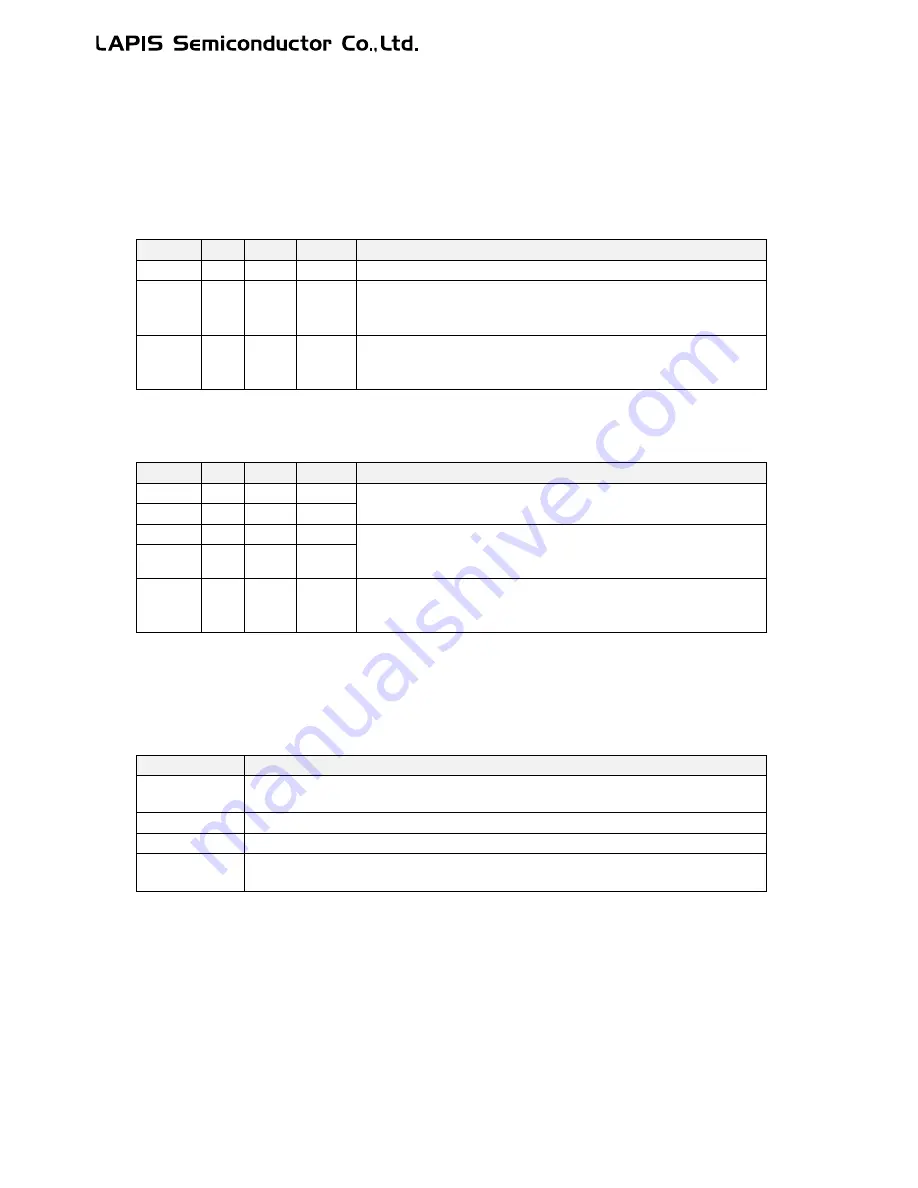
4.3.6 Note on Return Operation from Standby Mode
The operation of returning the standby mode is caused by the interrupt level (ELEVEL) of the program status word
(PSW), master interrupt enable flag (MIE), the contents of the register (IE0 to IE7), non-maskable interrupt, or maskable
interrupt. The operation varies depending on the cause. See "nX-U16/100 Core Instruction Manual" for details of PSW
and Chapter 5 "Interrupts" for IE and IRQ registers respectively. Tables 4-1 and 4-2 show the return operations from the
standby mode for non-maskable interrupt and maskable interrupt respectively.
Table 4-1 Return Operation from Standby Mode (for Non-Maskable Interrupt)
ELEVEL
MIE
IEn.m
IRQn.m
Return operation from standby mode
X
X
-
0
Not returned from the standby mode.
3
X
-
1
After returning from the standby mode, the program operation restarts
from the instruction next to the instruction that enters the standby
mode. The program operation does not go to the interrupt routine.
0,1,2
X
-
1
After returning from the standby mode, the program operation restarts
from the instruction next to the instruction that enters the standby
mode. Then the program operation goes to the interrupt routine.
n=0 to 7, m=0 to 7
X: Value-independent
Table 4-2 Return Operation from Standby Mode (for Maskable Interrupt)
ELEVEL
MIE
IEn.m
IRQn.m
Return operation from standby mode
X
X
X
0
Not returned from the standby mode.
X
X
0
1
X
0
1
1
After returning from the standby mode, the program operation restarts
from the instruction next to the instruction that enters the standby
mode. The program operation does not go to the interrupt routine.
2,3
1
1
1
0,1
1
1
1
After returning from the standby mode, the program operation restarts
from the instruction next to the instruction that enters the standby
mode. Then the program operation goes to the interrupt routine.
n=0 to 7, m=0 to 7
X: Value-independent
The ELEVEL of PSW has bits that indicate the state of interrupt process performed by the CPU It is set by the hardware
when transferring to the interrupt process or returning from the interrupt.
Table 4-3 State of CPU-Processed Interrupt Indicated by ELEVEL
ELEVEL value
State of CPU-processed interrupt
0
Indicates that the CPU is not processing any interrupt (non-maskable interrupt, maskable
interrupt, software interrupt).
1
Indicates that the CPU is processing a maskable or software interrupt.
2
Indicates that the CPU is processing a non-maskable interrupt.
3
Indicates that the CPU is processing an emulator-dedicated interrupt. Usually this is not
used in the software.
[Note]
Ÿ
Since up to two instructions are executed during the period between the release of standby mode and a
transition to interrupt processing, place two NOP instructions next to the instruction set for the standby
mode. When a master interrupt enable (MIE) flag of the program status word (PSW) in the nX-U16/100
CPU core is "1", following the execution of the two NOP instructions, the interrupt transition cycle will
be executed and execution of the instruction for interrupt routine begins. If MIE is "0", following the
execution of the two NOP instructions, the instruction execution is continued from the one that follows
the NOP instruction without transition to the interrupt.
Ÿ
When the CPU operation mode is “Wait mode”, the PLL reference frequency is 24MHz and the MIE bit is
“0”, choose 12MHz or slower as the SYSTEMCLK before entering the standby modes.
Содержание ML62Q1000 Series
Страница 17: ...Chapter 1 Overview...
Страница 112: ...Chapter 2 CPU and Memory Space...
Страница 154: ...Chapter 3 Reset Function...
Страница 166: ...Chapter 4 Power Management...
Страница 196: ...Chapter 5 Interrupts...
Страница 248: ...Chapter 6 Clock generation Circuit...
Страница 274: ...Chapter 7 Low Speed Time Base Counter...
Страница 291: ...Chapter 8 16 Bit Timer...
Страница 320: ...Chapter 9 Functional Timer FTM...
Страница 382: ...Chapter 10 Watchdog Timer...
Страница 402: ...Chapter 11 Serial Communication Unit...
Страница 456: ...Chapter 12 I2 C Bus Unit...
Страница 491: ...Chapter 13 I2 C Master...
Страница 512: ...Chapter 14 DMA Controller...
Страница 531: ...Chapter 15 Buzzer...
Страница 550: ...Chapter 16 Simplified RTC...
Страница 559: ...Chapter 17 GPIO...
Страница 594: ...Chapter 18 External Interrupt Function...
Страница 612: ...Chapter 19 CRC Generator...
Страница 632: ...Chapter 20 Analog Comparator...
Страница 644: ...Chapter 21 D A Converter...
Страница 655: ...Chapter 22 Voltage Level Supervisor...
Страница 676: ...Chapter 23 Successive Approximation Type A D Converter...
Страница 709: ...Chapter 24 Regulator...
Страница 714: ...Chapter 25 Flash Memory...
Страница 743: ...Chapter 26 Code Option...
Страница 750: ...Chapter 27 LCD Driver...
Страница 788: ...Chapter 28 On Chip Debug Function...
Страница 795: ...Chapter 29 Safety Function...
Страница 813: ...Appendix A...
Страница 881: ...Revision History...