242
8
CO/O
2
Control
Resetting Faults
Faults are reset in different ways:
Resetting temporary faults (ot):
The fault is displayed for as long as it is present. Once the cause of the fault is eliminated, the
fault is deleted, and the fault status signal no longer displayed.
Resetting permanent faults (od) at startup of the burner:
Each time the burner starts up, a fault is automatically reset, even if the cause of the fault has
not yet been eliminated. If the cause has not yet been eliminated, the fault will re-occur.
Resetting permanent faults (od) manually:
You can also reset permanent faults (od) manually after eliminating the cause.
UI400: Open the fault status signal using the arrow keys (see chapter
edge the fault with
.
CMS Remote Software: Use the RESET buttons in the header bar of the CMS Remote Soft-
ware.
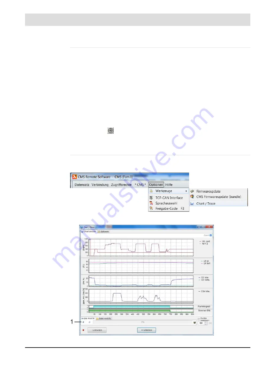
Chart/Trace (Recording Tool)
The recording tool can be used to record and store various values for evaluation and docu-
mentation purposes.
Fig. 8-34 Chart/Trace menu
Fig. 8-35 Chart view
Содержание CMS
Страница 1: ...www lamtec de Sensors and Systems for Combustion Engineering Manual Combustion Management System CMS...
Страница 2: ......
Страница 42: ...41 4 CMS Components 4 2 5 Terminal Assignment Fig 4 9 AEC TPS 230 VAC or 120 VAC terminal assignment...
Страница 131: ...130 7 Operating Control and Displays 7 1 5 5 Deleting Curves Delete firing rate curve...
Страница 142: ...141 7 Operating Control and Displays Accessing channel information AL1 Fig 7 12 GUI6xx channel information...
Страница 148: ...147 7 Operating Control and Displays Channel configuration AL1 Fig 7 18 Channel configuration...
Страница 154: ...153 7 Operating Control and Displays Accessing the CO O2 settings AL2 Fig 7 24 CO O2 settings menu...
Страница 157: ...156 7 Operating Control and Displays Fig 7 27 System CRCs menu...
Страница 162: ...161 7 Operating Control and Displays Fig 7 32 IP setting menu...
Страница 163: ...162 7 Operating Control and Displays 7 2 8 User Settings Accessing the display settings Fig 7 33 Display settings menu...
Страница 164: ...163 7 Operating Control and Displays Accessing the language settings AL1 Fig 7 34 Language settings menu...
Страница 166: ...165 7 Operating Control and Displays Fig 7 35 Installation...
Страница 167: ...166 7 Operating Control and Displays Fig 7 36 Installation...
Страница 176: ...175 7 Operating Control and Displays Fig 7 49 Loading a protected dataset into the device...
Страница 198: ...197 7 Operating Control and Displays 1 Digital inputs 2 Digital outputs 3 PLC Signals 4 Analogue measurement values...
Страница 202: ...201 7 Operating Control and Displays Replacing a Module Fig 7 81 Module replacement menu...
Страница 271: ...270 10 Maintenance 6 Close the window Connection between PC and CMS is established Indication of the con nected CMS...
Страница 272: ...271 10 Maintenance How to update the firmware in the CMS AL2 1 Open the menu Firmware update 2 Prepare firmware update...
Страница 274: ...273 10 Maintenance Activating the Debug Data 1 Start CMS Remote Software 2 Set device online 3 Show debug data...
Страница 276: ...275 10 Maintenance 3 Restart CMS to complete the update...
Страница 282: ...281 12 Appendix 12 5 EU Declaration of Conformity...
Страница 283: ...282 12 Appendix...


