2NL/2P8-4
1-5-39
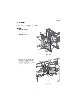
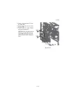
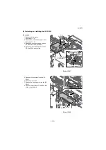
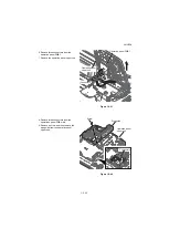
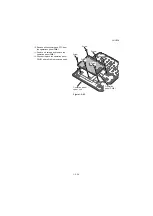
7. Remove eight screws and remove the
controller box cover.
Figure 1-5-67
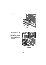
8. Remove five connectors, three USB
and FFC from the main PWB.
9. Remove six wire holders and release
the wires and FFC.
10. Remove the connector of the controller
fan motor from the main PWB.
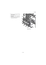
11. Unhook two hooks of the wire guide
and then remove the wire guide from
the controller box.
Figure 1-5-68
Screw
Screw
Screws
Screw
Screw
Screw
Screws
Screw
Controller box cover
Wire guide
Wire holder
Connector
Controller box
Hook
Hook
Connectors
FFC
USB
Содержание TASKalfa 3010i
Страница 1: ...SERVICE MANUAL Published in September 2016 842NL11B 2NLSM06B Rev B TASKalfa 3010i TASKalfa 3510i ...
Страница 10: ...This page is intentionally left blank ...
Страница 100: ...2NL 2P8 1 2 76 This page is intentionally left blank ...
Страница 286: ...2NL 2P8 1 3 186 This page is intentionally left blank ...
Страница 443: ...2NL 2P8 1 5 59 This page is intentionally left blank ...
Страница 463: ...2NL 2P8 2 1 18 Figure 2 1 23 Duplex conveying section block diagram EPWB DU_SENS DU_CL_REM YC14 5 YC8 1 DUCL DUS ...
Страница 471: ...2NL 2P8 2 2 8 This page is intentionally left blank ...
Страница 532: ...Installation Guide DP 770 B Document processor DP 772 Document processor Installation Guide ...
Страница 568: ...DP 773 Document processor Installation Guide ...
Страница 594: ...PF 791 500 x 2 Paper feeder Installation Guide ...
Страница 602: ...PF 810 3000 sheet deck Installation Guide ...
Страница 615: ...DF 791 3000 sheet finisher Installation Guide ...
Страница 630: ...DF 770 D 1000 sheet finisher Installation Guide ...
Страница 648: ...AK 740 Bridge unit Installation Guide ...
Страница 650: ...MT 730 B Mailbox Installation Guide ...
Страница 665: ...PH 7A C D Punch unit Installation Guide ...
Страница 686: ...DT 730 B Document tray Installation Guide ...
Страница 731: ...5 2013 5 302LC56750 01 H F G D D 6 4 3 7 E C D D M4 8 M4 8 M4 8 M4 8 ...
Страница 732: ...FAX System W B Installation Guide ...

