background image

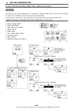
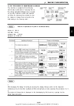
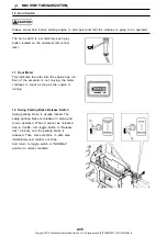
Level gauge (Only for Australia spec.)By

monitoring this level-gauge, you can learn

whether this machine is kept in a horizontal

position.

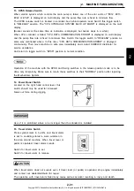
To light the cab working light, press the

symbol side of this switch.

16. Level Gauge (Only for Australia spec.)

17. Cab Working Light (Option)

Regarding how to use the cab working light switch, refer to "7.4 CAB WORKING LIGHT SWITCH".

2. MACHINE FAMILIARIZATION

2-32

Copyright © 2015 Kobelco Construction Machinery Co.,Ltd. All rights reserved. [S2YF00022ZE01]  [0731CsCshWbYs]

Содержание SK235SR-2

Страница 1: ...YU06 03014 READ UNDERSTAND AND FOLLOW ALL SAFETY PRECAUTIONS AND INSTRUCTIONS FOUND IN THIS MANUAL BEFORE OPERATING THE MACHINE Printed in Japan 2010 11 KE Destination AUS Copyright 2015 Kobelco Cons...

Страница 2: ...Copyright 2015 Kobelco Construction Machinery Co Ltd All rights reserved S2YF00022ZE01 0731CsCshWbYs...

Страница 3: ...INE FAMILIARIZATION 2 1 BASIC COMPONENTS OF THE MACHINE 2 3 2 2 OPERATOR CAB NOMENCLATURE 2 4 2 3 COMPONENT CONTROLS NOMENCLATURE 2 5 2 3 1 GAUGE CLUSTER 2 5 2 3 2 LOCATION OF SWITCHES AND METERS 2 26...

Страница 4: ...PARTS 4 14 4 6 TORQUE VALUES FOR SPECIFIED 4 15 4 7 TORQUE SPECIFICATIONS FOR BOLTS NUTS 4 17 4 8 TORQUE SPECIFICATIONS FOR JOINTS HYDRAULIC HOSES 4 20 4 9 INSPECTION MAINTENANCE CHART 4 22 4 10 WHEN...

Страница 5: ...INTERVAL 7 13 7 1 10 REINFORCING ATTACHMENT 7 13 7 1 11 PROHIBITED WORK IN USE OF NIBBLER 7 14 7 1 12 PRECAUTION TO BE EXERCISED ON BREAKERS OF DIFFERENT MANUFACTURES 7 16 7 2 ROTARY MULTI CONTROL VA...

Страница 6: ...Copyright 2015 Kobelco Construction Machinery Co Ltd All rights reserved S2YF00022ZE01 0731CsCshWbYs...
Страница 7: ...FOREWORD FOREWORD 0 1 Copyright 2015 Kobelco Construction Machinery Co Ltd All rights reserved S2YF00022ZE01 0731CsCshWbYs...

Страница 8: ...FOREWORD 0 2 Copyright 2015 Kobelco Construction Machinery Co Ltd All rights reserved S2YF00022ZE01 0731CsCshWbYs...
Страница 9: ...Maintenance procedures are completely understood This manual describes the basic operating techniques Skill is gained as the operator utilizes these techniques and perfects them with an actual machine...

Страница 10: ...e to non observance of simple safety norms and elementary precautions Many accidents can be avoided if the causes are known and opportune cautions taken beforehand There is no device or protection no...

Страница 11: ...istributor of your machine s Serial Number and Engine Serial Number stamped in the locations and Hour Meter read shown on the illustrations below For future reference record these Serial Numbers in th...

Страница 12: ...laced by HINO 2 OWNER S WARRANTY RESPONSIBILITIES As the heavy duty off road engine owner you are responsible for the performance of the required maintenance listed in your owner s manual HINO recomme...

Страница 13: ...emperature and time sensitive valves and switches B Electronic control units sensors solenoids and wiring harnesses C Hoses belts connectors assemblies clamps fittings tubing sealing gaskets or device...

Страница 14: ...FOREWORD 0 8 Copyright 2015 Kobelco Construction Machinery Co Ltd All rights reserved S2YF00022ZE01 0731CsCshWbYs...
Страница 15: ...1 SAFETY PRECAUTIONS 1 SAFETY PRECAUTIONS 1 1 Copyright 2015 Kobelco Construction Machinery Co Ltd All rights reserved S2YF00022ZE01 0731CsCshWbYs...
Страница 16: ...1 SAFETY PRECAUTIONS 1 2 Copyright 2015 Kobelco Construction Machinery Co Ltd All rights reserved S2YF00022ZE01 0731CsCshWbYs...

Страница 17: ...death of personnel Therefore all precautionary measures NOTES DANGERS WARNINGS and CAUTIONS contained in this manual and on the machine should be read and understood by all personnel before starting...

Страница 18: ...der the machine Hang a Do Not Operate tag in the Operator s Compartment 5 Do not work on any machine that is supported only by lift jacks or a hoist Always use blocks or jack stands capable of support...

Страница 19: ...are bent or damaged Inspect lines tubes and hoses carefully Do not check for leaks with your hands Very small pinhole leaks can result in a high velocity oil stream that will be invisible close to th...

Страница 20: ...ciency particulate air HEPA filter d Use exhaust ventilation on permanent machining jobs e Wear an approved respirator if there is no other way to control the dust f Comply with applicable rules and r...

Страница 21: ...e the attached warning labels and decals Confirm whether labels can be easily read If words or illustrations are illegible clean off or replace the labels Use a cloth water and detergent to clean the...

Страница 22: ...cing or repairing machine keep surfaces free of oil water grease tools etc to avoid possible slipping and or falling from machine which can cause personal injury Located on top of hydraulic tank Part...

Страница 23: ...to negative battery terminal of normal battery Connect other end of booster cable to upper frame of troubled machine 3 Start engine and remove booster cables in reverse order 4 WORKING ABOVE GROUND Do...

Страница 24: ...with cloth rag Loosen cap slowly to relieve pressure Located on top of engine fan shroud Part Number YN20T01009P1 Rotating parts can cause personal injury Keep away from fan and belt when engine is r...

Страница 25: ...ausing severe injury Keep face and body away from grease fitting area Do not loosen grease fitting more than one turn If grease does not release after one turn of the fitting call our dealer distribut...

Страница 26: ...affected areas immediatery with clean water and seek medical attention Located on battery cover Part Number YN20T01001P1 Located on battery cover Part Number PY20T01069P1 Located on seat stand Part Nu...

Страница 27: ...down of the housed front window resulting in injury Located on counterweight right rear side Part Number YN20T02100P1 18 LOCK FRONT WINDOW AT THE HOUSED POSITION 19 CAUTION FOR REPLACEMENT OF FILTER...

Страница 28: ...to NORMAL position and contact our service shop immediately 20 TRAVEL SPEED ADJUSTING TRACK TENSION LEAVING MACHINE READ OPERATOR MANUAL POWER BOOST SWITCH ENGINE STOP BUCKET TO CAB CONTACT ELECTRICA...

Страница 29: ...0 hrs Located on arm Part Number YN20T01337P1 2 REQ D Make sure the area is clear of obstacles and persons before begining the operation of the machine Always look around before you start the swing op...

Страница 30: ...r Part Number YN20T01039P1 OPT Located on fuel tank Part Number YF20T01197P1 OPT 25 OPERATION BY FOOT PEDAL 26 NIBBLER BREAKER OPERATION POSITION 27 ROTARY MULTI CONTROL VALVE 28 ROTARY MULTI CONTROL...

Страница 31: ...e to turn off the AIS system when using machine for lifting work Make sure the following cautions when using Auto Idle Stop AIS system After AIS system activates and stops engine make sure to turn the...

Страница 32: ...operating inspecting and serving the machine follow the precaution and procedure for the safety described in this manual Never operate machine when being in poor physical condition having taken medici...

Страница 33: ...ve guard and cover and mirror are installed properly If the failure is found repair it immediately Well understand how to use the device for safety Never remove the device for safety and control it so...

Страница 34: ...o remove mud grease and oil etc on the sole of shoes The sole with mud grease and oil etc might slip on the pedal when operating resulting in accident Do not leave parts and tools in the area around t...

Страница 35: ...il antifreeze mixture window washer etc Follow precaution described below Fire due to Faulty Electric Wire The fire may be caused by short circuit of electric wire Keep all connectors of electric wire...

Страница 36: ...achine while holding tools by hand The large noise from the surrounding might cause hard hearing and deafness If it is unavoidably necessary to enter in noisy area for long time do not fail to wear pr...

Страница 37: ...structions in the manual accompanying the optional attachment Use of any optional attachment not approved by manufacturer in writing can cause serious injury to personnel damage to the machine and its...

Страница 38: ...heck that the control lever pedal and switch can be properly manipulated U ADJUSTMENT OF OPERATOR S SEAT Adjust the operator s seat to the body of operator and the working contents or operator might b...

Страница 39: ...n seat belt without fail whenever taking the seat Check the attaching bracket and attaching belt for possible failure before fastening the seat belt Replace seat belt at least every 3 years even thoug...

Страница 40: ...eed while keeping the position of attachment close to the ground H CONFIRM OPERATING CONTROL PATTERN Slowly operate the control levers to confirm the operating patterns in advance Make sure the operat...

Страница 41: ...ng over and skidding Keep the bucket at the height of 20 to 30 cm 0 7 to 1 ft from the ground in order to make putting it down to the ground at emergency possible Do not turn the direction and go acro...

Страница 42: ...travel controls Sound horn before operating swing travel machine If necessary have a flagman signal operator during operation to prevent injury to persons or damage to obstacles and equipment O OPERAT...

Страница 43: ...ith limited height and swing traveling areas such as tunnels bridges around electrical power lines other utilities or inside structures Use extreme caution on work sites with limited height and swing...

Страница 44: ...sition the crawler at right angle to shoulder and the travel motors to the rear of the machine allowing for quick reversal should the work area become unstable U CHECK THAT NO PERSON IS UNDER THE BUCK...

Страница 45: ...traffic to avoid accidents AA WORK WITH SUFFICIENT LIGHTING When working in dark places turn on the work lamp And if required provide additional lighting facilities to assure good visibility Stop wor...

Страница 46: ...ht of the machine could cause shoulder of road or pathway to become loose or unstable Inspect the areas where the machine will travel and operate on to assure safe operation is possible Pay attention...

Страница 47: ...ange filters 1 6 INSPECTION MAINTENANCE SAFETY A READ CAREFULLY OPERATING MAINTENANCE PROCEDURES Incorrect maintenance may cause not only damages on the machine but also injury Read and fully understa...

Страница 48: ...or inspection or maintenance carry out the work with two people The person seated in the operator s seat should be ready to stop the engine at any time while watching for a signal from the other perso...

Страница 49: ...m when working above ground In addition strap yourself to the proper equipment accordingly Avoid spillage of any oil or grease Do not leave any tools around the working area Use extreme caution to avo...

Страница 50: ...nnectors may cause damaging Attach welder ground cable near the weld area Futhermore the cable attached are is to be positioned at the same welding area Make sure that neither bearing nor seal are the...

Страница 51: ...ing when lessening crawler belt tension Never loosen grease fitting more than one complete turn See 4 39 for the procedures to adjust the tension of the crawler belt track S PAYING ATTENTION TO BROKEN...

Страница 52: ...proper operation Increase the engine speed gradually and again check for leakages and abnormalities Operate each control lever carefully for smooth operation W DISPOSE OF WASTE PROPERLY X OPENING AND...

Страница 53: ...ode if you try to charge the battery or you try to jump start and run the engine To prevent the explosion warm the battery to 16 deg C or higher When the battery electrolyte is frozen the battery can...

Страница 54: ...f the negative booster cable black to the upper frame of disabled machine away from the battery 7 Start the engine of boost vehicle and run it for about 10 minutes at high idle 8 Start the engine of d...

Страница 55: ...ATION The following examples of machine abuse and misuse should never be attempted by even the most experienced operator Such abuse and misuse of this machine and its attachments can result in serious...

Страница 56: ...sides of boom and bucket cylinder hose do not come into contact with ground When lowering the boom to the lower limit be careful in order that the boom does not interfere with crawler shoe This machi...

Страница 57: ...problem areas found before restarting the machine 6 If performing the machine storage in cold climates it may be necessary to remove the batteries from the machine and store in a warm well ventilated...

Страница 58: ...shock load onto the towing rope Do not use eyes on machine lower frame to tow machine Keep the wire rope horizontally and perpendicular to the crawler frame Tow the machine slowly in low speed mode Fo...

Страница 59: ...isibility can not be ensured sufficiently provide a flagman in the working areas Follow the instructions of flagman and pay attention to the signal The signal shall be given by one flagman When workin...

Страница 60: ...1 SAFETY PRECAUTIONS 1 46 Copyright 2015 Kobelco Construction Machinery Co Ltd All rights reserved S2YF00022ZE01 0731CsCshWbYs...

Страница 61: ...the mirror Regarding visible range refer to previous page Mirror B Adjust mirror so that person who stands on the right rear ends of machine or post of 1 5m high and 30cm in diameter can be identifie...

Страница 62: ...to the shaded range on 1 11 Mirror D Adjust the mirror so that the ground within the range of 1 m in surroundings behind the machine can be identified from the operator s seat Install mirror to the po...

Страница 63: ...2 MACHINE FAMILIARIZATION 2 MACHINE FAMILIARIZATION 2 1 Copyright 2015 Kobelco Construction Machinery Co Ltd All rights reserved S2YF00022ZE01 0731CsCshWbYs...
Страница 64: ...2 MACHINE FAMILIARIZATION 2 2 Copyright 2015 Kobelco Construction Machinery Co Ltd All rights reserved S2YF00022ZE01 0731CsCshWbYs...
Страница 65: ...27 Travel Motor 6 Fuel Tank 17 Operator Cab 28 Battery 7 Swing Motor 18 Track Shoe Assembly 29 Engine Radiator 8 Swivel Joint 19 Track Idler 30 Oil Cooler 9 Boom Cylinder 20 Track Spring 31 Engine Hoo...

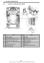
Страница 66: ...Power Boost Switch 24 Fuse Relay Box 11 Starter Key Switch 25 Travel Alarm Switch 12 Throttle Potentiometer 26 Level Gauge 13 Attchment Mode Select Switch Option 27 Cab Working Light Switch Option 14...

Страница 67: ...ic excavator All personnel associated with this machine should read and understand this information BEFORE beginning any work with or on this equipment 2 3 1 GAUGE CLUSTER When caution sign was displa...

Страница 68: ...ume of fuel in the fuel tank Refuel when the indicator is approaching to the E point Refill the fuel tank with diesel fuel only For fuel in use see 4 3 LUBRICANT FUEL COOLANT SPECIFICATIONS 1 WHITE Op...

Страница 69: ...buzzer stop switch 1 and buzzer shown below stops sounding 1 SCREEN CHANGE SWITCH If the screen change switch is not operated for 30 seconds keeping the screen for maintenance displayed the screen au...

Страница 70: ...2 MACHINE FAMILIARIZATION 2 8 Copyright 2015 Kobelco Construction Machinery Co Ltd All rights reserved S2YF00022ZE01 0731CsCshWbYs...
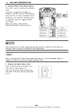
Страница 71: ...nozzle of front window while the switch is being pressed The washer tank is located on the rear side of cab 3 WORK KPSS MODE SELECT SWITCH As for the work mode after the engine starts the mode that wa...

Страница 72: ...required HIGH 2nd speed rabbit Set to HIGH when moving the machine on flat hard ground 5 WIPER SWITCH When the wiper switch is operated the indication of Intermittent or Continuous appears on the low...

Страница 73: ...ated the engine speed rises back to the accel dial set level gradually according to the respective operating pilot valve stroke Anytime this switch is deactivated OFF the engine speed rises to the acc...

Страница 74: ...h see the following 8 1 Auto Warming Up to 8 5 Pump Flow Rate Adjustment Nibbler mode Breaker mode Press screen change switch 1 during the above adjustment and setting operations and the screen return...

Страница 75: ...d then if it is in low temperature the automatic warming up operation starts Pull up the safety lock lever to lock it 6 In warming the engine oil and hydraulic oil the AUTO WARM UP is displayed on the...

Страница 76: ...make sure to turn the auto idling stop switch OFF When you start the engine again after an auto idling stop start after once returning a key switch at ACC or OFF and also returning a throttle potentio...

Страница 77: ...operation of FEED 4 the AUTO IDLING STOP OFF screen d is displayed 4 In operation of FEED 4 the color of OFF portion reverses and the AUTO IDLING STOP OFF screen e is displayed 5 Switch from OFF to ON...

Страница 78: ...then press select switch 8 and the ADJUST CLOCK ADJUST CONTRAST screen d is displayed 3 In operations of FEED 4 and FEED 5 move cursor to ADJUST CLOCK and then press select switch 8 and the ADJUST CLO...

Страница 79: ...s of FEED 4 and FEED 5 move cursor to ADJUST CLOCK ADJUST CONTRAST and then press select switch 8 and the ADJUST CLOCK ADJUST CONTRAST screen e is displayed 4 Press select switch 8 and the ADJUST CONT...

Страница 80: ...cording to some kind of attachment it is required to change the flow rate for service circuit Change the flow rate in accordance with the procedure mentioned below In this machine last set flow rate h...

Страница 81: ...splayed 4 When the nibbler breaker select screen b or c is displayed press the select switch 8 and the value of flow rate reverses to black and the screen is changed to d To increase flow press the up...

Страница 82: ...er to the section of Maintenance The gauge cluster processes signals received from various sensors and switches and outputs the signals to LCD display and lamp display and makes the buzzer sound The e...

Страница 83: ...me the travel low and high speed change switch is pressed and the selected mode is displayed 3 Auto accel display Press auto accel switch 3 and the icon Auto Accel is displayed to inform that auto acc...

Страница 84: ...reen displays the remaining time to the end of recommended replacement interval specified for filter oil After reaching to the end of replacement interval check and serve them following to section Mai...

Страница 85: ...of parts is mentioned below Engine oil 500 Hr Fuel filter 500 Hr Hydraulic filter 1 000 Hr Hydraulic oil 5 000 Hr 1 After displaying the display for setting by pressing the display change switch set...

Страница 86: ...rity to level 2 When these warning are displayed there is a possibility of serious trouble Therefore stop the operation immediately investigate the causes and take a proper measure 1 WARNING CLASSIFIC...

Страница 87: ...2 MACHINE FAMILIARIZATION 2 25 Copyright 2015 Kobelco Construction Machinery Co Ltd All rights reserved S2YF00022ZE01 0731CsCshWbYs...

Страница 88: ...Release Switch 5 Conflux Single Flow Change Switch Option 14 Power Boost Switch 6 Tuner 15 Travel Alarm Switch 7 Air Conditioner Control Panel 16 Level Gauge 8 Cap For Opt Switch 17 Cab Working Light...

Страница 89: ...be released to go back to the ON position 1 Starter Key Switch The starter key switch is located on the right hand operator console and has 4 operating functions 2 Throttle Potentiometer The throttle...

Страница 90: ...ft and deck right go on Press the side without symbol mark and the work lights on the boom left and deck right go off 3 Attachment Mode Select Switch Option When attachment has not been appropriately...

Страница 91: ...volt power supply and insert 24 volt male socket into power supply Replace cover after use 5 Conflux Single Flow Change Switch This switch is used to switch the single flow and conflux hydraulic circu...

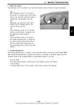
Страница 92: ...en it cannot be unlocked due to trouble turn toggle switch to Release lock unlock and the parking brake is released Then move machine to safe area immediately and contact our shop And return to toggle...

Страница 93: ...ROR is displayed on multi display and the pump flow rate is fixed to minimum flow Switch this toggle switch to RELEASE position as same way mentioned above In this case CPU DATA COMMUNICATION ERROR is...

Страница 94: ...he cab working light press the symbol side of this switch 16 Level Gauge Only for Australia spec 17 Cab Working Light Option Regarding how to use the cab working light switch refer to 7 4 CAB WORKING...

Страница 95: ...tion securely Make sure that the safety lock lever is held to the locked position shown in the figure When unlocking do not touch other levers unintentionally If touches other lever unintentionally th...

Страница 96: ...s illustrated in the right Confirm for safety around the working area Also ensure that each lever operation is in accordance with the operating pattern indicated on the labels If labels do not match t...

Страница 97: ...fting the control lever When operating the control lever make sure the crawler frame direction When the travel motor is located on the front side the travel lever functions of the travel levers will b...

Страница 98: ...led may cause serious accident resulting in injury and death 2 3 4 FUSES RELAY BOX Make sure the starter key switch is in the OFF position when replacing fuses The fuses protect the electrical system...

Страница 99: ...Hand Control 29 15A Engine Controller ECU 10 5A Relay Hour Meter 30 5A Gauge Cluster Back Up 11 10A Cigarette Lighter 31 15A Fuel Supply Pump 12 10A Horn Horn Relay 32 5A Mechatro Controller Back Up 1...

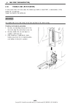
Страница 100: ...in position 2 3 5 FUSIBLE LINK FOR STARTER In case power does not come when the starter key switch is turned ON a disconnection of the fusible link is suspected Inspect and replace the fusible link Th...

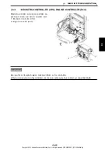
Страница 101: ...6 MECHATRO CONTROLLER CPU ENGINE CONTROLLER ECU Be careful not to splash water mud and drinks on the controllers When error occurred on the controller do not take self service but contact our dealer...

Страница 102: ...RADIO A EXPLANATION OF UNITS 1 Name and How to Use of Each Unit 1 Power switch 2 AM FM switch key 3 Volume control 4 UP DOWN key 5 Preset key 6 DISP display change key 7 Sound control key 8 Display Ti...

Страница 103: ...and display is switched to FM1 FM2 AM in order When the band is switched the station received before switching is selected 3 Display switching 4 Band switching 5 How to select station This radio can s...

Страница 104: ...eeping as it is 1 Press the tone control key 7 for 1 second or more The desired station starts the presetting 2 During presetting the display A moves from left to right 3 After auto presetting this fu...

Страница 105: ...he required radio station by changed frequency 5 3 2 Manual preset Press one of the 6 PRESET keys 5 for 1 second or more The currently received station is memorized in the pushed button of preset No 5...

Страница 106: ...anges continuously up and down 3 After operation of the volume control key the display returns to the frequency or the time display The Balance and Tone are adjustable with this key Balance adjustment...

Страница 107: ...raise the volume of a right speaker push the DOWN 4 key while BAL is displayed 1 To emphasize the treble push the UP key 4 while TRE is displayed To weaken the treble push the DOWN key 4 while TRE is...

Страница 108: ...ey 4 To decrease Hour press the DOWN key 4 3 Press DISP key 6 again and the Minute display flickers 4 To decrease Minute press the UP key 4 5 Press DISP key 6 again and the time setting is completed T...

Страница 109: ...start the engine at slow speed Do not start the air conditioner at high speed This might cause failure of air conditioner Pay attention to the control panel and solar radiation sensor E so as not to s...

Страница 110: ...proper mode manually through recirculate and fresh air capacity selector switch 2 and compressor switch 3 ON OFF 3 Select preferable fan speed manually through fan speed selector switch 4 when fan spe...

Страница 111: ...h AUTO 1 and fan speed and air outlet are automatically controlled and AUTO indicator lamp on LCD display is illuminated c When the main power switch 6 is OFF the system will retain the previous setti...

Страница 112: ...pressing of the switch d The set temperature 18 5C degrees 65 3F degrees is the lowest cooling temperature and 31 5C degrees 88 7F degrees is the highest heating temperature Control beyond either of t...

Страница 113: ...ulation B Fresh Air Intake 5 Defroster Switch and Display 6 Recirculate and Fresh Air Selector Switch and Display 7 Compressor Switch and Display Press compressor switch 3 in the condition where mark...

Страница 114: ...ason In and Off 1 Season in Contact our dealer distributor for checking and service of air conditioner before air cooling season season in so that the air conditioner is used in good condition for a l...

Страница 115: ...BELT Install the seat belt properly or the fundamental performance may not be achieved Make sure that there is no abnormality on the belt attaching bracket and bolts before fastening the belt Check at...

Страница 116: ...until arm rest is in desired position To fine adjust the angle of arm rest turn control dial 8 F Head Rest Adjustment 1 Move head rest 6 forward or backward to desired reclining angle G Lumber Support...

Страница 117: ...position with bolt 1 3 Similarly adjust stand height on the other side by procedure 1 and 2 A Low position B Middle position C High position 2 3 11 ARM REST ADJUSTMENT The height of right left arm res...

Страница 118: ...After the control lever is unexpectedly touched without the safety lock lever locked this may cause serious accident resulting in injury and death A Cab Door Lock This is used to fix door in the condi...

Страница 119: ...rd and lock it securely C Opening and Closing Front Window The front window should be opened and closed in the condition where the machine is parked in level and locked securely If the lock is release...

Страница 120: ...the left rear side of cab securely a Turn cab lamp ON by pushing the lamp switch way up b The lamp goes out at the neutral position c Turn OFF by pushing switch all the down ward D Removing Storing Lo...

Страница 121: ...rear window glass by using life hammer 1 4 If it is impossible to use rear windows for escape open and escape from the skylight 2 3 14 EMERGENCY ESCAPE FROM CAB For how to open the front window see it...

Страница 122: ...with starter key This is provided on the inside of cover on the left rear side of machine When the gun is not used put it on this holder This is provided on the right side console in the cab This is...

Страница 123: ...3 MACHINE OPERATION 3 MACHINE OPERATION 3 1 Copyright 2015 Kobelco Construction Machinery Co Ltd All rights reserved S2YF00022ZE01 0731CsCshWbYs...
Страница 124: ...3 MACHINE OPERATION 3 2 Copyright 2015 Kobelco Construction Machinery Co Ltd All rights reserved S2YF00022ZE01 0731CsCshWbYs...
Страница 125: ...d remove as required 3 Check the hydraulic equipment hydraulic oil tank hoses and joints for oil leakage and repair as required 4 Check the travel system such as the crawler idlers and sprockets for a...

Страница 126: ...key 3 1 2 CHECKING BEFORE STARTING ENGINE The following checkup should be performed once before the first engine startup in a day A Checking Coolant Level for Shortage and Making Up Do not open radia...

Страница 127: ...gher than H level connect drain hose H to engine drain plug P and drain excess engine oil And be sure to check oil level again 6 If the oil level is proper insert level gauge G securely close engine h...

Страница 128: ...up all spilled fuel to prevent fire Dispose of all hazardous waste in accordance with government environmental laws and regulations It is possible to operate machine for 2 days 8 hours a day in gener...

Страница 129: ...arter key unlock side door on left side of counterweight and open it 2 By visual check check mud dust and leaves which contaminate filters 1 and 2 3 When filter is contaminated heavily refer to 4 14 2...

Страница 130: ...to 176 F degree F Check Hydraulic Oil Level It is very danger because the inside of hydraulic tank is heated and pressurized When removing filler port plug stop engine and remove breather top end cap...

Страница 131: ...0 28 7 to 8 mm 0 28 to 0 31 28 6 3 G Checking Belt Tension Rotating parts can cause injury Keep away from fan and belt when engine is running Stop engine before servicing When replace with new belt th...

Страница 132: ...d to the back seat 3 1 3 ADJUSTING OPERATOR SEAT Adjust the operator seat before starting operation or at the time when operator was changed Be careful not to put hands between handle and seat stand F...

Страница 133: ...Before any working make sure that the mirrors are correctly adjusted If the mirror position is incorrectly adjusted the best all around operator view is not obtained This can result in serious injury...

Страница 134: ...ly the light bulb is burned out or electrical wire is broken Contact our dealer distributor for repair 3 1 5 CHECKING FUNCTION OF GAUGE CLUSTER Before starting the engine check the warning display and...

Страница 135: ...ing position But it is impossible to start the engine again until the buzzer stops sounding after the engine stops When necessary to leave from the operator seat for a long time turn starter key switc...

Страница 136: ...e NEUTRAL position 3 Set throttle potentiometer 2 to low idling position 4 Turn the starter key 3 to ON position and confirm the operating condition of multi display 5 Turn the starter key switch 3 to...

Страница 137: ...attempt to start the disabled machine Either allow batteries to thaw and then charge or replace the batteries Follow the order indicated in the next page for connecting or disconnecting the booster c...

Страница 138: ...isabled machine 9 After starting the engine of disabled machine remove the booster cables in the reverse order of the above connection order 10 Check and repair the cause of the problem of the chargin...

Страница 139: ...re 4 Turn the starter key switch 2 to OFF to stop the engine 5 Remove the starter key switch 2 3 1 8 STOPPING MACHINE ENGINE Run the engine for at least 5 minutes at low speed before stopping Avoid da...

Страница 140: ...unexpected movement of the machine Set the safety lock lever to the locked up position before leaving the cab Make sure the swing area of machine is clear of people and obstacles before operating Know...

Страница 141: ...ay When warning was displayed on the multi display stop the engine immediately and investigate the cause of error Check the exhaust gas color After warming up and at no load Colorless or light blue No...

Страница 142: ...ming up is necessary Perform the warming up by the following procedure A Engine Warm Up The revolution up of engine while idling may cause failure and trouble to the engine Do not revolution up the en...

Страница 143: ...nutes relief operation And then extend and or retract the rod of each cylinders several times slowly for the purpose of circulating of warm hydraulic oil Also operate swing and travel slowly and circu...

Страница 144: ...ter the engine starting is always the start from S mode S mode is suitable for standard digging and loading works and is in saving fuel consumption and is in good balance to the workload H mode is sui...

Страница 145: ...y closely Turn the attachment mode switch to a correct position when the switch position is improper Match the attachment mode to the attachment that is used from now Select the breaker mode absolutel...

Страница 146: ...of the CONTROLS decal located on the right side window inside the operator cab Study this decal and understand the directions each control can be operated and the functions associated with each movem...

Страница 147: ...ound horn Do not permit for people to gain access to the machine If the operation of control lever in auto accel operation could cause abrupt increase of engine speed Pay attention to the operation Th...

Страница 148: ...ng for the machine is that the travel motor is on the rear side and the track idler is on the front side Sound horn to warn workers in the site B 1 Forward Reverse Travel Forward Reverse Travel Do not...

Страница 149: ...witch panel is available to change the travel speed from to low speed 1st speed to from high speed 2nd speed When starting engine the switch is automatically set to low speed 1st speed The mode is cha...

Страница 150: ...t stop it after slow traveling Return the right and left travel levers 1 to neutral N position The machine stops traveling 3 MACHINE OPERATION 3 28 Copyright 2015 Kobelco Construction Machinery Co Ltd...

Страница 151: ...o not allow large or heavy objects to strike travel motors 10 Do not travel over large objects such as boulders rocks etc 11 If necessary to travel or operate machine in a river or other water the bed...

Страница 152: ...on the ground and pushing the boom and arm against the ground Raise the crawler belt track a small distance off the ground Scrape the mud sand or gravel off the crawler belts tracks This material may...

Страница 153: ...e bucket attachment only If other attachments are being used consult the operator s manual for the particular attachment Read understand and follow all safety precautions during all operations of this...

Страница 154: ...t a safe distance away from cab to avoid damage or injury G 4 Swing Operation Use swing flashers during swing operations Swing operation is performed by moving the L H control lever to the right and l...

Страница 155: ...system is designed for use during bucket digging operations when extra Break Out power is required to allow the bucket to break through a dig If the power boost switch is left depressed while perform...

Страница 156: ...e and its components Always point bucket teeth in the direction the machine will be digging to reduce digging resistance and the possibility of bucket teeth damage The attachment will provide maximum...

Страница 157: ...stop slewing action release the swing lever before you get to your final point of digging or dumping E Cleaning Sand Soil from Bucket Avoid shaking out soil using shocks at the end of the bucket cyli...

Страница 158: ...not to bump the reversed bucket into the cab 4 The excavating power during shovel operations is less than that during backhoe operations 5 If machine bucket is equipped with a lifting eye check to ma...

Страница 159: ...in direction of movement required 3 1 15 FLAGMAN HAND SIGNALS The following is a compilation of the hand signals to be used when a flagman is required for excavator operation All personnel associated...

Страница 160: ...umb up Face machine operator extend right arm out horizontally from shoulder make a fist with thumb down Face machine operator extend right arm out horizontally from shoulder make a fist with index fi...

Страница 161: ...at elbows with arms facing operator make fists and point thumbs out away from each other Face machine operator place right hand on top of hard hat bend left arm at elbow to the right make a fist with...

Страница 162: ...machine operator bend both elbows in make fists and rotate fists one over the other in a forward circular motion Face machine operator hold left hand in closed and stationary hold right hand in make a...

Страница 163: ...small reverse circular motion Face machine operator raise left forearm up make fist with left hand and hold stationary bend right arm in make fist with right hand and rotate right fist in a small for...

Страница 164: ...shoulder with hand open and facing down move arm in a horizontal motion back and forth Face machine operator raise both arms out horizontally from shoulders with hands open and facing down move arms i...

Страница 165: ...track dig bucket teeth into ground lower dozer blade if equipped to the ground This will help prevent machine movement Set the safety lock lever to the locked up position to avoid any unexpected mach...

Страница 166: ...xterior and travel system components If leakage and damage are found repair it immediately according to applicable procedure in Chapter 4 INSPECTION MAINTENANCE CHART 3 Fully refill with fuel However...

Страница 167: ...ort circuit and cause extensive damage to the machine systems Check the battery electrolyte acid level frequently and fill as necessary with distilled water If the machine will be left outside overnig...

Страница 168: ...in the radiator fins oil cooler fins or debris screen 3 Operation in High Altitudes a Due to low atmospheric pressure at high altitudes a decrease in engine power will be experienced Be aware of this...

Страница 169: ...4 MAINTENANCE 4 MAINTENANCE 4 1 Copyright 2015 Kobelco Construction Machinery Co Ltd All rights reserved S2YF00022ZE01 0731CsCshWbYs...
Страница 170: ...4 MAINTENANCE 4 2 Copyright 2015 Kobelco Construction Machinery Co Ltd All rights reserved S2YF00022ZE01 0731CsCshWbYs...

Страница 171: ...rmined by the hour meter If performing lubrication and maintenance according to calendar time is preferred the hour meter reading must correspond to the lubrication and maintenance period 8 H 50 H 120...

Страница 172: ...revent contamination from dust water etc The inspection and maintenance charts provided in this section give only general time intervals It may be necessary to develop a custom schedule to perform mac...

Страница 173: ...her inspection or maintenance procedures other than those specified in the manual Carry them out parking the machine at a flat and conveniently situated place Do not attempt any MAINTENANCE with engin...

Страница 174: ...OT OPERATE tag P N YN20T01320P1 to the operator s console to inform the operator that the machine will be inoperable for inspection and maintenance This tag will help prevent accidental starting of th...

Страница 175: ...termine any abnormal wear When a strainer is provided on the filling port do not remove it while refilling fuel oil or fluid H WARM ENGINE OIL Engine oil should have a temperature of between 20 to 40C...

Страница 176: ...under the boom arm or under the bucket attachment use proper equipments or blocks to secure the attachment M DISPOSAL OF HAZARDOUS WASTE CONTAMINATION HAZARDS Dispose of all hazardous waste in accorda...

Страница 177: ...especially starter and generator to not allow deposit of dust on them Q OPERATION IN DUSTY CONDITIONS When the machine is operated in dusty operating conditions do the following R CLEANING PARTS Use o...

Страница 178: ...s not located at a seal or bearing Do not locate welder ground at seal or bearing 5 Make sure that no bearings or seals separates the welder ground and the weld area S HYDRAULIC TANK PRESSURE Always r...

Страница 179: ...chart provides information on the specification of oils grease fuels and coolant to be used in various climates and working conditions 4 MAINTENANCE 4 11 Copyright 2015 Kobelco Construction Machinery...

Страница 180: ...th hot surfaces of flames may cause the Antifreeze Coolant to burn Repair leaks immediately and dispose of used Antifreeze Coolant promptly and in accordance with government environmental regulation 1...

Страница 181: ...draulic oil tank with new BIO oil 4 After starting engine move every cylinder 10 strokes respectively The abrupt operation may cause burning of seal because of trapped air in the cylinder Try to opera...

Страница 182: ...0A Cartridge 1 Every 500 hours Air conditioner YN50V01015P3 Air con filter Outer 1 Every 10 times cleanings When heavy clogging of filter occurs clean or replace YN50V01014P1 Air con filter Inner 1 Pi...

Страница 183: ...t and nut Check for any loose or missing bolts or nuts before daily operation and during periodical inspections Retighten or supply new parts for missing ones as required 4 MAINTENANCE 4 15 Copyright...

Страница 184: ...tions during swing operation How to check Strike the bolt head or nut by hand hammer lightly and find the looseness by catching dull sound Tighten bolts and nuts again if necessary 4 MAINTENANCE 4 16...

Страница 185: ...fer to the below table for proper tightening of bolts 4 7 TORQUE SPECIFICATIONS FOR BOLTS NUTS The torque values in the table do not apply for all bolts used with plastic covers For the tightening tor...

Страница 186: ...e thread standard tightening torque values Tighten all bolts and nuts to proper torque values 4 MAINTENANCE 4 18 Copyright 2015 Kobelco Construction Machinery Co Ltd All rights reserved S2YF00022ZE01...

Страница 187: ...e thread standard tightening torque values Tighten all bolts and nuts to proper torque values 4 MAINTENANCE 4 19 Copyright 2015 Kobelco Construction Machinery Co Ltd All rights reserved S2YF00022ZE01...

Страница 188: ...R JOINTS HYDRAULIC HOSES A Ors Joint O Ring Sealing Type B Nuts Sleeve C Joints for Piping D Hydraulic Hoses 4 MAINTENANCE 4 20 Copyright 2015 Kobelco Construction Machinery Co Ltd All rights reserved...

Страница 189: ...Flange These tightening torques are available in the case of tightening without lubricant 4 MAINTENANCE 4 21 Copyright 2015 Kobelco Construction Machinery Co Ltd All rights reserved S2YF00022ZE01 0731...

Страница 190: ...operation time shown by the hour meter whichever comes first See the inspection and maintenance procedure mentioned below for details See 4 3 LUBRICANT FUEL COOLANT SPECIFICATIONS for detail specific...

Страница 191: ...of radiator often Clean the filter and core depending on their dirt Contact our dealer distributor for checking and adjustment shown by asterisk 2 4 MAINTENANCE 4 23 Copyright 2015 Kobelco Constructi...

Страница 192: ...4 MAINTENANCE 4 24 Copyright 2015 Kobelco Construction Machinery Co Ltd All rights reserved S2YF00022ZE01 0731CsCshWbYs...
Страница 193: ...ttachment should lubricated every 250 hours of operation Next it should lubricated every 500 hours of operation but the lubrication around bucket has to be applied every 250 hours 4 MAINTENANCE 4 25 C...

Страница 194: ...UAL before operating or servicing the machine A Cleaning or Replacement of Radiator Cap To avoid being burned be careful when removing the radiator cap Coolant is under high pressure when hot Do not r...

Страница 195: ...Washer fluid reservoir 1 is located under of floor plate in cab D Replacement of Bucket AVOID INJURY Replace the bucket on firm level ground Pay close attention to safety The abrupt operation of front...

Страница 196: ...ightly raise the bucket from the ground 4 Align bucket 6 with the pin hole of arm 7 moving arm 7 and insert pin 5 5 Insert pin 3 and fix retaining ring 2 6 Fit O ring 1 to the normal position 7 Apply...

Страница 197: ...A Safety Block 1 Adapter Nose 2 Tooth Point 3 Rubber Lock 4 Locking Pin 5 Side Cutter 6 Bolt 7 Nut E Check for Abrasion Damages on Tooth Point Side Cutter When replacing the tooth point and side cutte...

Страница 198: ...dapter nose 1 5 Push the rubber lock pin 3 in the hole of the adapter nose 1 6 Hammer the locking pin 4 until it is aligned with the point surface E 1 Replacing the Tooth Points Wear goggles safety sh...

Страница 199: ...030 N m 680 to 760 lbf ft 3 After tightening the nuts spot weld them A Safety Block E 2 Replacing the Side Cutters Wear goggles safety shoes hard hat work clothes and work gloves to perform inspection...

Страница 200: ...retaining ring and pin 8 After attaching rotate bucket softly to the stroke end in engine low idling condition and check that there is no interference of each section F Reversing Backhoe Bucket The b...

Страница 201: ...e regular position to the bucket boss position 3 Swing rightward slightly and press the arm top end against the bucket right side On this side there is not looseness adjustment mechanism 4 Move safety...

Страница 202: ...ead and understand the 1 SAFETY PRECAUTIONS of this MANUAL before operating or servicing the machine The following inspection and maintenance shall be carried out before starting after starting and af...

Страница 203: ...pin 7 6 Arm cylinder rod pin 8 7 Arm to boom pin 9 8 Bucket cylinder head pin 10 9 Bucket link pins 11 10 Bucket cylinder rod pin 12 11 Idler link to arm pin and arm to bucket pin 13 12 Arm top pin 1...

Страница 204: ...y fluid has strong acid It corrodes metal very rapidly If it adheres on skin or enters into eye it causes for a burn or blindness At such case immediately wash skin or eye with lots of water and ask a...

Страница 205: ...Clean battery terminal and apply grease or commercial lube oil rust preventive spray Call in licensed specialty company for the disposal of used battery Be careful not to use the old battery together...

Страница 206: ...lean up all spilled fuel Fuel oil is highly flammable Spilled fuel can cause fires 1 Swing the upper structure of the machine so that the drain valve 1 under the fuel tank comes to midway between the...

Страница 207: ...ches 5 To decrease track tension set machine up as shown in figure 6 Carefully loosen the adjusting grease nipple 1 to allow grease to escape 7 Tighten grease nipple 1 measure track tension as shown i...

Страница 208: ...body away from grease nipple area Never loosen grease nipple more than one complete turn If grease does not release after one turn of the nipple call an authorized KOBELCO service dealer for assistanc...

Страница 209: ...2 with light oil and wind seal tape on tube 3 and install plug securely Tightening torque 49 4 to 60 4 N m 36 to 45 lbf ft 4 13 120 HOUR INSPECTION MAINTENANCE PROCEDURE Thoroughly read and understand...

Страница 210: ...l plug 3 with light oil and then attach it in place 4 Similarly check on the travel reduction unit on the other side B Travel Reduction Unit Oil Travel reduction unit could be under pressure Carefully...

Страница 211: ...me time with new parts C Checking for Intake Rubber Hose Don t touch the rubber hose to avoid burns Immediately after stopping the machine or during the operation the temperature of the rubber hose is...

Страница 212: ...MANUAL before operating or servicing the machine Perform together with daily 50 hour and 120 hour inspection and maintenance A Fan Alternator A C Belt Wear and Tension Rotating parts can cause injury...

Страница 213: ...hood and support it with stay 2 Loosen nut 1 for idle pulley slightly and adjust the belt tension while turning the adjusting bolt 2 and then tighten nut 1 Tightening torque 41 2 to 51 0 N m 30 4 to...

Страница 214: ...p 1 immediately if the crack permanent set in fatigue and water leakage is found The immediate replacement could protect engine from serious failure like overheating etc D Checking the Radiator Hoses...

Страница 215: ...nt level is lower than the replacing hose 2 and drain coolant in container 4 Loosen clamp 1 remove damaged hose 2 and replace the hose with new one 5 Tighten drain valve 6 Fill coolant in radiator and...

Страница 216: ...air filter 2 through opening from which cover 1 is removed and pull it out upward E Air Conditioner Filters Service The flying debris due to compressed air may cause accident resulting in injury or d...

Страница 217: ...g Clean recirculation and fresh air filters Clean recirculation and fresh air filters by air blowing E 4 Attaching Procedure Attach recirculation and fresh air filters after cleaning or for replacemen...

Страница 218: ...engine first and clean and replace the air cleaner element Fro machines equipped with double element and the inner element 6 must be replaced together with the outer element 3 Do not fail to replace t...

Страница 219: ...r filter so that ARROW position mark is faced upward G Radiator and Oil Cooler Debris Screen Hot fluids and surfaces can burn Wear goggles safety shoes hard hat work clothes and work gloves to perform...

Страница 220: ...5 intercooler 6 and condenser 7 for clogging When mud dust and dead leaves are found clean them off depending on the degree of dirt 7 Remove dust mud and other dirt from their cores and fins using co...

Страница 221: ...ly 50 hour 120 hour and 250 hour inspection and maintenance A REPLACING ENGINE OIL AND ENGINE OIL FILTER Do not touch the heated section during operation or immediately after being stopped There is a...

Страница 222: ...hot after stopping engine Allow enough time for the engine to cool before inspection or maintenance to avoid being burned In this machine the engine oil filter is located at the separate position fro...

Страница 223: ...and lower limit crank engine and start the engine Stop engine after idling for several minutes and check the oil level after about 10 minutes and if the level is low fill oil pan with the specified e...

Страница 224: ...en an extra three quarters turn by the filter wrench Parts number 2421R171 Do not reuse element and O ring Clean the area of filter and replace it Especially clean the area of the air bleeding plug an...

Страница 225: ...r according to the air bleeding procedure for fuel system Dispose of all hazardous waste in accordance with government environmental regulations 4 MAINTENANCE 4 57 Copyright 2015 Kobelco Construction...

Страница 226: ...5 8 Fit case 3 to filter head by hand securely and tighten it with filter wrench Parts number 2421R171 C Replacing Pre Filter The pre filter is placed on the area where the inside of door on the mach...

Страница 227: ...from the Fuel System After replacing the fuel filter or if you have run out of fuel air might have entered the fuel system and a simple supply of fuel cannot start the engine Bleed the air according t...

Страница 228: ...te through grease nipple unteill the grease comes out from bearing seal when the direction of the slewing bearing is changed at every 90 degrees Grease amount Max 40 cc 1 grease nipple G Checking Slew...

Страница 229: ...boot H Lubricating Push Rod of Control Lever With Grease Remove rubber boot of pilot valve and apply a small amount of grease to the push rod and top end 2 of rotation sliding section Removing Boot 4...

Страница 230: ...re B Shows that the refrigerant is over charged I Checking the Air Conditioner Refrigeran Do not loosen parts in the refrigerant circuit because there is a hazard of losing sight by getting coolant in...

Страница 231: ...minutes to rotate the compressor regardless of the season This will prevent the refrigerant gas from leaking from the compressor sealing When oil comes out from the pipe joint contact our dealer dist...

Страница 232: ...removing the cover The oil is under high pressure when hot Stop engine first remove breather cap press valve release the pressure from tank and then remove cover Immediately after operation there is...

Страница 233: ...element assy B while turning the handle Disassembling parts B C D E F 7 Replace O ring C of check valve B 8 Replace packing F of plate E 9 Replace element and assemble element assy A disassembled in p...

Страница 234: ...the nut 3 and set the seal 2 8 Rotate the breather cap 1 in a clockwise tightly by hand And then install the breather cap 1 B Replacement of Air Breather Element The components of machine stay hot aft...

Страница 235: ...iately wash skin or eye with lots of water and ask a doctor to treat it as soon as possible Stop the engine and carry out maintenance and checking service for the battery Remove battery terminal from...

Страница 236: ...the coolant is hot The cooling system is under pressure Stop the engine and allow enough time for system to cool Engine anti freeze coolant liquid is flammable and can cause injury Keep anti freeze co...

Страница 237: ...After discharging water clean it with cleaning solution Regarding to how to use cleaning solution follow the instructions in Instruction Manual for the cleaning solution in use 9 After cleaning open...

Страница 238: ...edge of radiator filler cap and then tighten radiator cap 15 Replace the support of stay close engine hood and lock hood with starter key 12 Run engine by low idling for 5 minutes to remove air contam...

Страница 239: ...range of level gauge 3 it is normal level 6 Clean filling plug 2 with light oil and wind seal tape on tube 4 and install plug securely Tightening torque 48 5 to 60 4 N m 36 to 45 lbf ft B Changing Oil...

Страница 240: ...l hazardous waste in accordance with government environmental regulations C Change Oil in Travel Motor Reduction Units Immediately after operation there is a hazard of getting burn because oil is hot...

Страница 241: ...mounting bolts 2 of tank upper cover remove cover 3 D Cleaning Suction Strainer Use extreme caution when removing the cover The oil is under high pressure when hot Stop engine first remove breather ca...

Страница 242: ...eturn the machine to the hydraulic level checking position Stop the engine and check the oil level if the level is low make up the oil 1 Park machine on firm level ground and place the attachment to t...

Страница 243: ...ing 3 with new one After cleaning apply Loctite 572 for prevention from water intruding 3 Grease may be cloudy due to slight contamination of water but there is no malfunction if the viscosity is high...

Страница 244: ...Line Filter Immediately after operation there is a hazard of getting burn due to hot hydraulic oil gushed Clean the filter after being cooled Carry out the replacement of filter after completely rele...

Страница 245: ...00 hour inspection and maintenance A Change Hydraulic Oil Use extreme caution when removing the cover The oil is under high pressure when hot Stop engine first remove breather cap press valve release...

Страница 246: ...torque 98 to 118 N m 72 to 87 lbf ft 11 Fill hydraulic tank with hydraulic oil through filler port Fill with hydraulic oil watching the level gauge 5 for oil level 12 Attach filler port cover 4 with 6...

Страница 247: ...ers Then lower boom until attachment is resting on the floor 6 Coat cylinder rods with a heavy coat of grease to prevent corrosion during storage 7 Remove batteries and store in a well ventilated warm...

Страница 248: ...m travel motor and slewing gear reduction units to drain off any moisture which may have accumulated during storage 3 Carefully and closely inspect all hydraulic hoses after long periods of storage fo...

Страница 249: ...5 TRANSPORTATION 5 TRANSPORTATION 5 1 Copyright 2015 Kobelco Construction Machinery Co Ltd All rights reserved S2YF00022ZE01 0731CsCshWbYs...

Страница 250: ...5 TRANSPORTATION 5 2 Copyright 2015 Kobelco Construction Machinery Co Ltd All rights reserved S2YF00022ZE01 0731CsCshWbYs...

Страница 251: ...es overpasses height of road signs on route 3 Obtain any permits required from proper government agencies for machine transportation 4 Use only a trailer with a rated capacity sufficient to transport...

Страница 252: ...is transported remove the bucket as shown in the above figure to limit the overall height of the machine within 3 8 m 12 6 5 TRANSPORTATION 5 4 Copyright 2015 Kobelco Construction Machinery Co Ltd Al...

Страница 253: ...eling is necessity to load and unload the machine It is hazardous to use the attachment for loading and unloading the machine Do not use the attachment for loading and unloading Use only the traveling...

Страница 254: ...on turn the upper structure 180 degrees slowly 8 After positioning lower attachment softly To prevent the arm and bucket cylinder s from any damage you are advised to follow the following instructions...

Страница 255: ...of truck trailer 4 At loading the machine climb up to the truck trailer from front end of the machine for the case of the machine with attachment and from back end for the machine without attachment...

Страница 256: ...ed to fix the machine 5 1 3 SECURING THE MACHINE Retract the antenna of radio during transport And remove mirror when required Keep the removed parts surely To protect the bucket attachment cylinder f...

Страница 257: ...this time the bucket position should be close to ground To prevent the arm and bucket cylinders from any damage you are advised to follow the following instructions Do not have the arm and or bucket...

Страница 258: ...slip of the machine when lifted resulting in serious injury or death or damage to the machine When lifting the machine operate the controls slowly and smoothly avoiding any sudden fast control movemen...

Страница 259: ...g the procedure and remove or secure them 4 Stop the engine and remove starter key and get off the machine 5 Use wire rope and expander of sufficient length to prevent interference with the machine bo...

Страница 260: ...g in injury and death To avoid the damage or break do not install the mirror and so on to the handrail of cab entrance If the mirror and so on is installed to the hand rail the attaching part of handr...

Страница 261: ...n the mirror Regarding visible range refer to previous page Mirror B Adjust mirror so that person who stands on the right rear ends of machine or post of 1 5m high and 30cm in diameter can be identifi...

Страница 262: ...fer to the shaded range on 5 3 Mirror D Adjust the mirror so that the ground within the range of 1 m in surroundings behind the machine can be identified from the operator s seat Install mirror to the...

Страница 263: ...6 SPECIFICATIONS 6 SPECIFICATIONS 6 1 Copyright 2015 Kobelco Construction Machinery Co Ltd All rights reserved S2YF00022ZE01 0731CsCshWbYs...

Страница 264: ...6 SPECIFICATIONS 6 2 Copyright 2015 Kobelco Construction Machinery Co Ltd All rights reserved S2YF00022ZE01 0731CsCshWbYs...
Страница 265: ...Under Carriage mm ft in 455 1 5 G Radius of Rear End mm ft in 1 730 5 8 H Overall Length of Crawler mm ft in 4 260 14 0 4 640 15 3 I Center Distance of Tumblers mm ft in 3 470 11 5 3 850 12 7 J Ground...

Страница 266: ...to Top Cab mm 3 170 3 170 3 170 Ground Clearance of Undercarriage mm 455 455 455 Overall Length of Crawler mm 4 640 4 640 4 640 Overall Width of Crawler mm 3 190 3 190 3 190 Ground Pressure kPa 53 46...

Страница 267: ...RKING RANGES A Backhoe Attachment Marked dimensions do not include height of shoe lug 6 SPECIFICATIONS 6 5 Copyright 2015 Kobelco Construction Machinery Co Ltd All rights reserved S2YF00022ZE01 0731Cs...

Страница 268: ...B Face Shovel Attachment Marked dimensions do not include height of shoe lug 6 SPECIFICATIONS 6 6 Copyright 2015 Kobelco Construction Machinery Co Ltd All rights reserved S2YF00022ZE01 0731CsCshWbYs...
Страница 269: ...m is installed When the 2 94 m 9 8 arm is used do not reverse the bucket If the bucket is reversed the bucket bumps against arm by shoveling and it results damaging attachment Standard combination Gen...

Страница 270: ...6 SPECIFICATIONS 6 8 Copyright 2015 Kobelco Construction Machinery Co Ltd All rights reserved S2YF00022ZE01 0731CsCshWbYs...

Страница 271: ...7 OPTIONAL EQUIPMENT 7 OPTIONAL EQUIPMENT 7 1 Copyright 2015 Kobelco Construction Machinery Co Ltd All rights reserved S2YF00022ZE01 0731CsCshWbYs...

Страница 272: ...7 OPTIONAL EQUIPMENT 7 2 Copyright 2015 Kobelco Construction Machinery Co Ltd All rights reserved S2YF00022ZE01 0731CsCshWbYs...

Страница 273: ...hydraulic breaker or nibbler to prevent them from invasion of dust water etc Before the operation check the looseness on the clamps which are fixing the piping for attachment and the leakage on connec...

Страница 274: ...t and breaker are damaged Lower the attachment to the ground and confirm safety before you change the attachment mode Especially the load that is held by the nibbler falls during changing from the nib...

Страница 275: ...r OFF OFF Breaker ON Breaker ON ON Work mode and hydraulic circuit When the breaker is installed make sure to select the breaker mode because the return circuit should return the oil to the return fil...

Страница 276: ...ools 1 Arm Spanner 24 mm 7 1 5 SETTING STOP VALVE Tools used 7 1 6 FLOW RATE CONTROL The flow rate of service circuit may be changed according to attachment in use For the flow rate setting procedure...

Страница 277: ...ecification through switch 1 on the rear side of driver s seat A Breaker and Nibbler Selector Switch Do not set this switch to nibbler combined flow operation position when using breaker When nibbler...

Страница 278: ...side Breaker Nibbler Foot pedal depressing section Operation Foot pedal depressing section Operation Depess toe section A Breaker starts operation Depess toe section A Nibbler close Pedal in neutral p...

Страница 279: ...Device make sure to set the pedal lock to LOCKED position while the breaker or nibbler is not used Unexpected contact with UNLOCKED position of pedal may cause severe injury or death Do not put foot o...

Страница 280: ...hocks This may damage the rod seal and piston and cause oil to leak from those sections 7 1 8 PROHIBITED WORK IN USE OF BREAKER The following safety precautions should be used in conjunction with all...

Страница 281: ...minute intervals Operation for longer than 1 minute at a time can cause high oil temperatures and the accumulators cylinder seals and possibly pump damage Should the hydraulic hoses begin to surge or...

Страница 282: ...achment The breaker is rusted and results in damage of sealing Consequently contamination with rust dust and water enter into hydraulic oil This causes damage of hydraulic equipment The balance on the...

Страница 283: ...problems with control valves early wear and possible seizure of the hydraulic pump leading to break down of the machine hydraulic system Operation of breaker accelerates the deterioration of hydraulic...

Страница 284: ...K IN USE OF NIBBLER The wrong nibbler operating method may cause damage of attachment and excavator or result in dangerous work condition To prevent these trouble learn correct and safety operating me...

Страница 285: ...cause damage of cylinder link and rod pin Do not operate the attachment over the sides of the machine It may cause rollover of machine And do not operate the machine abruptly but operate it slowly E D...

Страница 286: ...URES There are some differences between manufactures as to the piping to breakers and the handling of breakers For this reason consult with the manufacturer when mounting a breakers in the field The f...

Страница 287: ...ure exceeds 5 4 MPa 55 kgf cm2 780 psi install a low pressure accumulator Max 5 4 MPa 55 kgf cm 780 psi Regarding the capacity and the charge pressure of accumulators contact the breaker manufacturer...

Страница 288: ...multi control valve 1 A Lever of Rotary Multi Control Valve 1 Park the machine in condition of parking posture and stop the engine And shift safety lock lever to Locked position 2 Using starter key to...

Страница 289: ...esired one Stop engine and move the lever to each operation position once every 500 hours Make sure to return the lever to the position of former operation pattern 7 OPTIONAL EQUIPMENT 7 19 Copyright...

Страница 290: ...fore operating the machine or any attachment 1 Start machine and place the safety lock lever in the UNLOCKED down position 2 Move throttle control to the HI idle position 3 Using boom arm and bucket c...

Страница 291: ...nt Do not strike any obstacles such as large rocks The dozer blade may be damaged When the dozer blade is used as an outrigger do not support the machine at one end of the dozer blade Make sure the su...

Страница 292: ...ith reference to the following table Location of lubrication points Lubricate all grease nipples in the figure Blade foot pin 2 places Dozer cylinder rod head each 2 places 7 OPTIONAL EQUIPMENT 7 22 C...

Страница 293: ...9 10 2990 9 10 B Blade Height mm inch 684 2 3 684 2 3 R Distance From Dozer Attaching Pin Center To Blade End mm ft in 1910 6 3 2 1910 6 3 2 7 3 5 BLADE DIMENSION 7 OPTIONAL EQUIPMENT 7 23 Copyright 2...

Страница 294: ...ab working light press the symbol side of this switch 1 Press the symbol side The light is ON Press the blank side The light is OFF 7 4 CAB WORKING LIGHT SWITCH 7 OPTIONAL EQUIPMENT 7 24 Copyright 201...

Страница 295: ...8 SPECIAL PROCEDURES 8 SPECIAL PROCEDURES 8 1 Copyright 2015 Kobelco Construction Machinery Co Ltd All rights reserved S2YF00022ZE01 0731CsCshWbYs...

Страница 296: ...8 SPECIAL PROCEDURES 8 2 Copyright 2015 Kobelco Construction Machinery Co Ltd All rights reserved S2YF00022ZE01 0731CsCshWbYs...

Страница 297: ...ertain chock blocks are secure at front and rear of each track before attempting to release brakes Never stand in the path of the tracks when releasing brakes Read understand and follow all safety pre...

Страница 298: ...ting and holding 45 kg 100 lb 7 Torque wrench 70 to 77 N m 52 to 57 lbf ft capacity or better 8 Thread sealant For drain and check fill plugs 9 Rubber or soft faced mallet 8 2 RELEASING TRAVEL MOTOR B...

Страница 299: ...res See Fig 8 18 3 Turn key switch OFF and remove key See Fig 8 2 4 Remove check fill plug from each travel motor using the 12 mm socket head wrench See Fig 8 3 5 Place a clean 6 liter 1 6 Gal capacit...

Страница 300: ...14 Carefully by hand work the planetary gear assembly free from the housing See Fig 8 8 Fig 8 7 Fig 8 8 Be aware of and protect hands from pinch areas when removing and installing planetary gears or...

Страница 301: ...on both travel reduction units the machine may be towed to an area where repairs can be made 18 After repairs are made reinstall the drive gear in reverse order Use the following torque specification...

Страница 302: ...CCURS Fig 8 10 Fig 8 11 In highly contaminated environments it is recommended to remove the whole swing motor assembly if a hydraulic hand pump is not available Refer to the shop manual for special in...

Страница 303: ...brake Use safety protection such as hard hat working gloves safety shoes and safety glasses when needed to perform this job A Tools amp Equipment Required 1 Handtools required for removal of hydrauli...

Страница 304: ...ting eyes and remove most of the slack from the cable or chain 8 Carefully remove the remaining two bolts from the top mounting plate 9 Using the overhead lifting device carefully lift the swing motor...

Страница 305: ...move all brake springs and place in a container filled with fresh clean hydraulic oil Then seal the container to prevent contamination See Fig 8 15 11 Align the holes of the distributor plate in the s...

Страница 306: ...trouble etc After loosening lock nut of port relief valve as adjuster screw is loosened the set pressure gradually falls When the set pressure decreases lower than the hold pressure of cylinder curre...

Страница 307: ...ining in the boom cylinder head side returns to the tank through T port enabling attach ment to be lowered B How to Lower Attachment Fig 8 19 Fig 8 19 Before loosening adjuster screw mark those positi...

Страница 308: ...draulic tank Can be released by pushing valve on the air breather rubber cap several times 5 to 7 times Air breather mounted on the upper part of hydraulic tank 8 5 HYDRAULIC TANK PRESSURE 8 SPECIAL P...

Отзывы: