6 Troubleshooting
- 85 -
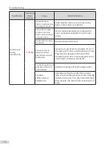
Fault Name
Operating
Panel
Display
Cause
Possible Solution
Power supply
unit fault
(continued)
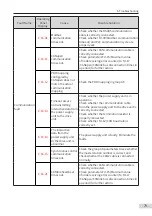
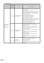
E 25.16
A communication
fault occurs.
1: Check whether the RS485 communication
cable is connected properly.
2: Check whether the setting of Fd-04
(Modbus communication timeout) and PLC
communication period are reasonable.
3: Check whether the CAN communication
cable is connected properly.
4: Check Fd-15 (Maximum value of node
receiving error counter) to Fd-17 (CANopen/
CANlink bus disconnection times in a period)
to obtain the interference information.
5: Check the PDO mapping of parameters in
group AF.
6: Check whether the power supply unit is
working.
7: Check whether the network cables are
connected for the power supply unit and drive
unit.
8: Check whether the termination resistor is
connected properly.
9: Check Fd-12 (CAN baud rate) to see whether
the CAN baud rate is consistent.
10: If the power supply unit is faulty, rectify the
fault.
11: Check Fd-15 (Maximum value of node
receiving error counter) to Fd-17 (CANopen/
CANlink bus disconnection times in a period)
to obtain the interference information.
12: Check the PDO mapping of parameters in
group AF.
13: Modify the CAN station numbers by using
Fd-13 (CAN station No.).
14: Check whether the PROFIBUS-DP cable is
connected properly.
15: Check whether the number displayed in
"The number of devices" of PLC matches the
actual quantity of stations.
16: Check whether the station numbers of
slaves are correctly set.
17: Check whether the value of “NO.n” of
PLC is consistent with that of AF-66/67 (Number
of valid RPDOs/Number of valid TPDOs).
18: Check whether the PROFIBUS-DP cable is
connected properly.
19: Check whether the value of "No.1" of PLC
is consistent with that of AF-66/67 (Number of
valid RPDOs/Number of valid TPDOs).
Содержание MD810 Series
Страница 1: ...User Guide MD810 Series Standard Drive Multidrive System A04 Data code 19010518 User Guide...
Страница 37: ...2 Installation 36 External 24 V power supply Connect with the drive unit terminal Figure e Figure f Figure g...
Страница 38: ...2 Installation 37 Figure h Figure i Figure 2 7 HST 6004 HST 7004 DC soft charge unit installation...

