Appendix A Parameter Table
- 92 -
Appendix A Parameter Table
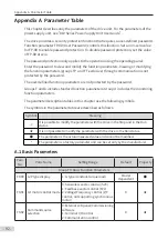
This chapter describes only the parameters of the drive unit. For the parameters of the
power supply unit, see "810 Series Power Supply Unit User Guide".
The drive provides a security protection function that requires a user-defined password.
Function parameter FP-00 (User Password) controls this function. Set a non-zero value
for FP-00 to enable password protection. To disable password protection, set the value
of FP-00 at zero.
The password protection only applies to the operation using the operating panel.
Enter the password to view and modify the function parameters. Viewing or modifying
the function parameters (groups FP and FF exclusive) through communication is not
protected by the password.
The user-defined function parameters are not protected by the password.
Groups F and A include standard function parameters. Group U includes the monitoring
function parameters.
The parameter description tables in this chapter use the following symbols.
The symbols in the parameter table are described as follows:
Symbol
Meaning
☆
It is possible to modify the parameter with the drive in the Stop and in the Run
status.
★
It is not possible to modify the parameter with the drive in the Run status.
●
The parameter is the actual measured value and cannot be modified.
*
The parameter is a factory parameter and can be set only by the manufacturer.
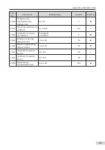
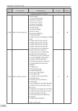
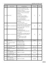
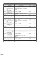
A.1 Basic Parameters
Para.
No.
Para. Name
Setting Range
Default
Property
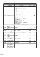
Group F0: Basic Function Parameters
F0-00
G/P type display
1: G type (constant-torque load)
Model
dependent
●
F0-01 1st motor control mode
0: Sensorless vector control (SVC)
1: Feedback vector control (FVC)
2: Voltage/Frequency control (V/F
control, not supporting synchronous
motor)
0
★
F0-02 Command source
selection
0: External LCD panel/Commissioning
software
1: Terminal I/O control
2: Communication control
0
★
Содержание MD810 Series
Страница 1: ...User Guide MD810 Series Standard Drive Multidrive System A04 Data code 19010518 User Guide...
Страница 37: ...2 Installation 36 External 24 V power supply Connect with the drive unit terminal Figure e Figure f Figure g...
Страница 38: ...2 Installation 37 Figure h Figure i Figure 2 7 HST 6004 HST 7004 DC soft charge unit installation...


