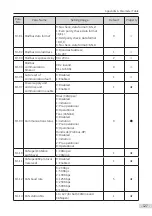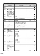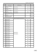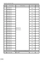
Appendix A Parameter Table
- 121 -
Para.
No.
Para. Name
Setting Range
Default
Property
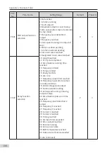
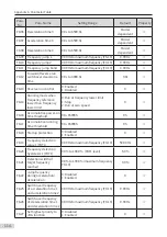
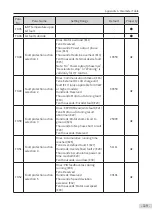
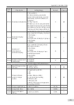
F9-69 Detection level of speed
deviation excessive
0.0% to 50.0% (maximum frequency,
F0-10)
0.0%: No detection
20.0%
☆
F9-70
Detection time of speed
deviation excessive
0.0s to 60.0s
5.0s
☆
F9-71
Power dip ride-through
gain
0 to 100
40
☆
F9-72
Power dip ride-through
integral coefficient
0 to 100
30
☆
F9-73
Deceleration time of
power dip ride-through
0.0 to 300.0s
20.0s
☆
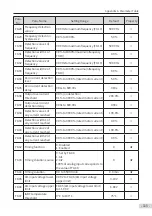
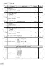
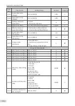
Group FA: Process Control PID Function
FA-00 PID reference setting
channel
0: FA-01
1: AI1
2: AI2
4: Pulse reference (DIO1)
5: Communication setting
6: Multi-reference
0
☆
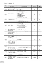
FA-01 PID digital setting
0.0% to 100.0%
50.0%
☆
FA-02 PID feedback setting
channel
0: AI1
1: AI2
3: AI1 – AI2
4: Pulse reference (DIO1)
5: Communication setting
6: AI1 + AI2
7: MAX (AI1, AI2)
8: MIN (AI1, AI2)
0
☆
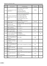
FA-03
PID operation direction 0: Forward
1: Reverse
0
☆
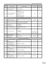
FA-04 PID reference and
feedback range
0 to 65535
1000
☆
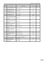
FA-05
Proportional gain Kp1
0.0 to 1000.0
20.0
☆
FA-06 Integral time Ti1
0.01s to 100.00s
2.00s
☆
FA-07 Differential time Td1
0.000s to 10.000s
0.000s
☆
FA-08 PID output limit in
reverse direction
0.00 Hz to maximum frequency (F0-10)
2.00 Hz
☆
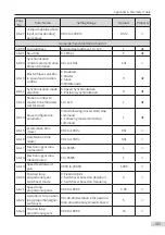
FA-09 PID deviation limit
0.0% to 100.0%
0.0%
☆
FA-10
PID differential limit
0.00% to 100.00%
0.10%
☆
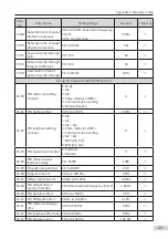
FA-11 PID reference change
time
0.00 to 650.00s
0.00s
☆
FA-12
PID feedback filter time
0.00 to 60.00s
0.00s
☆
FA-13
PID deviation gain
0.0% to 100.0%
100.0%
☆
Содержание MD810 Series
Страница 1: ...User Guide MD810 Series Standard Drive Multidrive System A04 Data code 19010518 User Guide...
Страница 37: ...2 Installation 36 External 24 V power supply Connect with the drive unit terminal Figure e Figure f Figure g...
Страница 38: ...2 Installation 37 Figure h Figure i Figure 2 7 HST 6004 HST 7004 DC soft charge unit installation...


