Appendix A Parameter Table
- 105 -
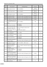
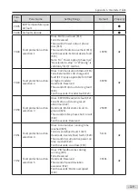
Para.
No.
Para. Name
Setting Range
Default
Property
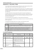
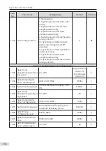
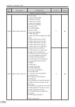
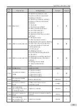
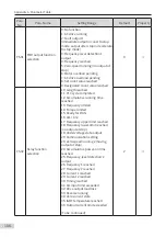
F4-02 Reserved
39: Switchover between main
frequency reference and preset
frequency reference
40: Switchover between auxiliary
frequency reference and preset
frequency
41: Reserved
42: Position lock enabled
43: PID parameter switchover
44: User-defined fault 1
45: User-defined fault 2
46: Speed control/Torque control
switchover
47: Emergency stop
48: External stop terminal 2
49: Deceleration DC injection braking
50: Clear the current running time
51: Two-wire control/ Three-wire
control switchover
52-53: Reserved
54: Winding diameter
55 to 56: Initial winding diameter
57: Pre-drive
58: Winding/Unwinding switchover
59: Winding diameter calculation
disabled
60: Exiting tension mode
61: Speed limit direction
(End)
9
★
F4-03 DIO1 function selection
12
★
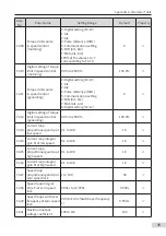
F4-04
DIO2 function selection
13
★
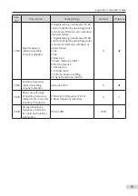
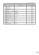
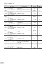
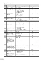
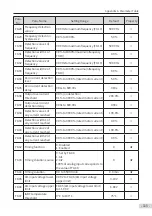
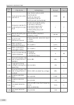
F4-10
DI filter time
0.000s to 1.000s
0.010s
☆
F4-11
Terminal I/O control
mode
0: Two-wire mode 1
1: Two-wire mode 2
2: Three-wire mode 1
3: Three-wire mode 2
0
★
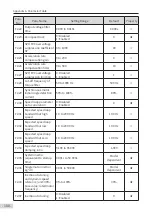
F4-12
Terminal UP/DOWN
change rate
0.001 to 65.535 Hz/s
1.000 Hz/s
☆
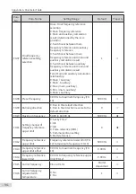
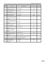
F4-13
AI curve 1 minimum
input
-10.00 V to F4-15 (AI curve 1
maximum input)
-10.00 V
☆
F4-14
Corresponding
percentage of AI curve
1 minimum input
-100.0% to +100.0%
-100.0%
☆
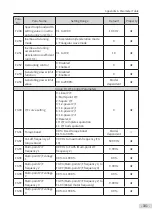
F4-15 AI curve 1 maximum
input
F4-13 (AI curve 1 minimum input) to
+10.00 V
10.00 V
☆
F4-16
Corresponding
percentage of AI curve
1 maximum input
-100.0% to +100.0%
100.0%
☆
Содержание MD810 Series
Страница 1: ...User Guide MD810 Series Standard Drive Multidrive System A04 Data code 19010518 User Guide...
Страница 37: ...2 Installation 36 External 24 V power supply Connect with the drive unit terminal Figure e Figure f Figure g...
Страница 38: ...2 Installation 37 Figure h Figure i Figure 2 7 HST 6004 HST 7004 DC soft charge unit installation...


