5 Quick Commissioning
- 62 -
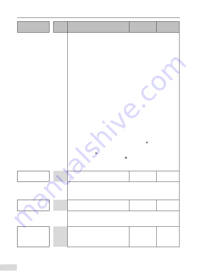
Operation
Para.
No.
Parameter Name
Default
Commission
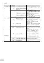
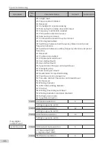
0: No operation
1: Asynchronous motor static auto-tuning
2: Asynchronous motor no-load complete auto-tuning
3: Asynchronous motor static complete auto-tuning
4: Asynchronous motor inertia auto-tuning (only FVC)
11: Synchronous motor no-load partial auto-tuning (back EMF
exclusive)
12: Synchronous motor dynamic no-load auto-tuning
13: Synchronous motor static complete auto-tuning
14: Synchronous motor inertia auto-tuning (only FVC)
NOTE:
If this parameter is set to1, 3, 11 or 13, the motor won’t rotate at
this stage. If this parameter is set to 2, 4 12 or 14, the motor will
rotate. It is better to disconnect the load from the motor shaft for
safety.
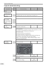
The auto-tuning procedure is as follows:
1)
Ensure the drive unit and the motor is not disconnected by an
output contactor; if it is, then manually handle with the output
contactor;
2)
Set F0-02 (Command source selection) to 0 (External LCD panel/
Commissioning software) to use the LED operating panel to
start the tuning procedure.
3) Set F1-37 (Auto-tuning selection) and press
ENTER
. The operating
panel will display letters "TUNE".
4) Hold down
ENTER
to enable the motor to start auto-tuning (auto-
tuning is canceled if you press
MODE
). It usually takes about 30
seconds to finish the auto-tuning. Wait until the LED stops
displaying "TUNE".
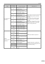
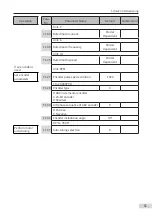
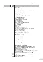
Select a
command source
F0-02 Command source selection
0
0: External LCD panel/Commissioning software
1: Terminal I/O control
2: Communication control
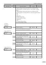
Select a control
mode
F0-01 1st motor control mode
0
0: SVC control
1: FVC control
2: V/F control(not supporting synchronous motor)
Select a
frequency
reference setting
channel
F0-03
Main frequency reference setting
channel selection
0
Содержание MD810 Series
Страница 1: ...User Guide MD810 Series Standard Drive Multidrive System A04 Data code 19010518 User Guide...
Страница 37: ...2 Installation 36 External 24 V power supply Connect with the drive unit terminal Figure e Figure f Figure g...
Страница 38: ...2 Installation 37 Figure h Figure i Figure 2 7 HST 6004 HST 7004 DC soft charge unit installation...


