3 Wiring
- 49 -
3.3.2 Descriptions of Control Terminals (Dual-axis)
AX2
STO
2
GND
2
1
GND
1
S1
24V
OP
COM
+10V
GND
AI1
DI1
DIO
1
A+
A-
B+
B-
Z+
Z-
5V
PGND
15V
1
2
3
4
5
6
7
8
9
CN
1
CN
4
CN3
CN
6
CN
2
12
TA
TB
TC
CN
5
DIP switch
Common terminal and
AI/
AO
/DI/
DO terminal
(axis 1)
Encoder
/
PG card terminal
(axis 1)
DP
communication
terminal
Relay terminal
AI2
DI2
DIO
2
A+
A-
B+
B-
Z+
Z-
5V
PGND
15V
Encoder
/
PG card terminal
(axis 2)
AI/
AO
/DI/
DO terminal
(axis 2)
AX1
STO
2
GND
2
1
GND
1
DIP switch
S2
12
3
RS485
terminal
CAN
2HC
AN
2L
CGND
C485+
C485-
CN
6
RJ45 communication
terminal
RJ45A
RJ45B
STO terminal
1
2
3
4
5
6
7
8
9
CN
6 Two
23
-bit encoders
1
2
3
4
5
6
7
8
9
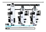
Figure 3-5
Control circuit terminal arrangement of the drive unit (dual-axis)
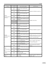
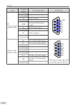
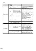
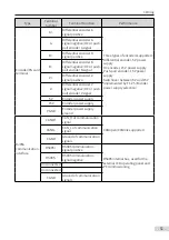
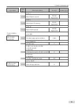
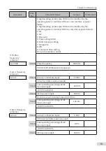
Table 3-5
Descriptions of control circuit terminals of the drive unit (dual-axis)
Type
Terminal
Symbol
Terminal Function
Performance
STO terminals
1
STO channel 1 power
positive
24 V power supply
1GND
STO channel 1 power
negative
2
STO channel 2 power
positive
2GND
STO channel 2 power
negative
Содержание MD810 Series
Страница 1: ...User Guide MD810 Series Standard Drive Multidrive System A04 Data code 19010518 User Guide...
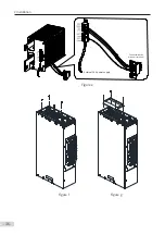
Страница 37: ...2 Installation 36 External 24 V power supply Connect with the drive unit terminal Figure e Figure f Figure g...
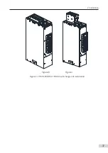
Страница 38: ...2 Installation 37 Figure h Figure i Figure 2 7 HST 6004 HST 7004 DC soft charge unit installation...


