3 Wiring
- 42 -
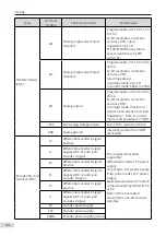
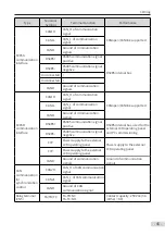
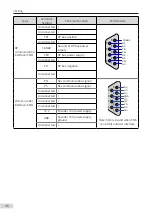
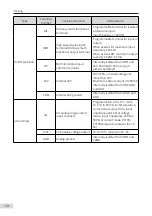
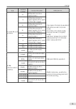
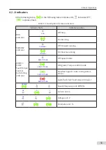
Table 3-3
Descriptions of control circuit terminals of the drive unit (single-axis)
Type
Terminal
Symbol
Terminal Function
Performance
STO terminals
1
STO channel 1 power positive
24 V power supply
1GND
STO channel 1 power negative
2
STO channel 2 power positive
2GND
STO channel 2 power negative
External 24 V
power terminal
DC24 V
External power 24 V power
positive
External power 24 V power
input for the internal control
module with the minimum
required current of 1 A
GND
External power 24 V power
negative
Connect with
the DC soft
charge unit
terminal
24 V_EXT
External DC soft charge unit
external power supply positive
External power 24 V power
input for the DC soft charge unit
with the minimum required
current of 1 A
OV_EXT
External DC soft charge
unit external power supply
negative
KIN1
DI input
Receiving responses from the
feedback module
KOUT
DO output
Controlling the operation of
relay and contactor
KIN2
DI input
Reserved
Содержание MD810 Series
Страница 1: ...User Guide MD810 Series Standard Drive Multidrive System A04 Data code 19010518 User Guide...
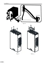
Страница 37: ...2 Installation 36 External 24 V power supply Connect with the drive unit terminal Figure e Figure f Figure g...
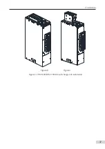
Страница 38: ...2 Installation 37 Figure h Figure i Figure 2 7 HST 6004 HST 7004 DC soft charge unit installation...


