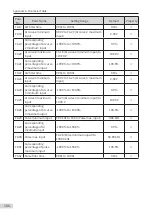
Appendix A Parameter Table
- 102 -
Para.
No.
Para. Name
Setting Range
Default
Property
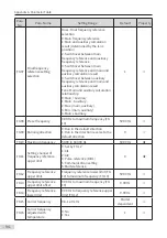
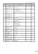
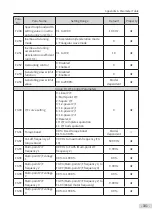
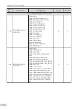
F3-09
V/F slip compensation
gain
0.0% to 200.0%
0.0%
☆
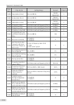
F3-10
V/F over-excitation gain 0 to 200
64
☆
F3-11
V/F oscillation
suppression gain
0 to 100
Model
dependent
☆
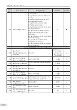
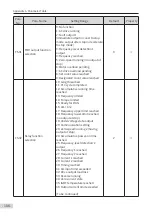
F3-12 Oscillation suppression
gain function
0: Disabled
3: Enabled
3
★
F3-13
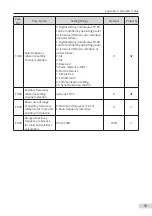
Voltage source for V/F
separation
0: Digital setting (F3-14)
1: AI1
2: AI2
4: Pulse reference (DIO1)
5: Multi-reference
0
☆
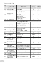
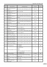
F3-14
Digital setting of
voltage for V/F
separation
0 V to rated motor voltage (F1-02)
0 V
☆
F3-15
Voltage rise time of V/F
separation
0.0s to 1000.0s
It sets the time for the output voltage
to rise from 0 to the rated motor
voltage (F1-02).
0.0s
☆
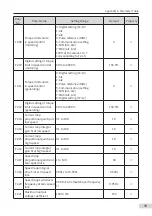
F3-16
Voltage decline time of
V/F separation
0.0s to 1000.0s
It sets the time for the output voltage
to rise from 0 to the rated motor
voltage (F1-02).
0.0s
☆
F3-17
Stop mode selection
for V/F separation
0: Frequency and voltage declining
to 0 independently
1: Frequency declining after voltage
declines to 0
0
★
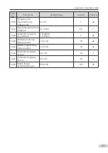
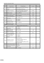
F3-18
Current limit level
50% to 200%
150%
★
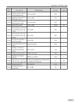
F3-19
Current limit selection 0: Disabled
1: Enabled
1
★
F3-20
Current limit gain
0 to 100
20
☆
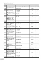
F3-21
Compensation factor
of speed multiplying
current limit level
50 to 200
50
★
F3-22
Voltage limit
650.0 to 800.0 V
770.0 V
★
F3-23
Voltage limit selection
0: Disabled
1: Enabled
1
★
F3-24
Frequency gain for
voltage limit
0 to 100
30
☆
F3-25
Voltage gain for voltage
limit
0 to 100
30
☆
Содержание MD810 Series
Страница 1: ...User Guide MD810 Series Standard Drive Multidrive System A04 Data code 19010518 User Guide...
Страница 37: ...2 Installation 36 External 24 V power supply Connect with the drive unit terminal Figure e Figure f Figure g...
Страница 38: ...2 Installation 37 Figure h Figure i Figure 2 7 HST 6004 HST 7004 DC soft charge unit installation...

