3 Wiring
R
S
T
+24V
OP
DI1
DI2
DI3
DI4
DI5
COM
CGND
C485-
C485+
T3C
T3B
T3A
L1
L2
L3
+
BR
Fault reset
(F4-00 = 5)
(F4-01 = 0)
(F4-02 = 0)
(F4-03 = 0)
(F4-03 = 0)
Modbus-RTU
Grounding screw
Communication
interface
45 kW model
Relay output:
250 VAC, 10 mA to 3 A
30 VDC, 10 mA to 1 A
Fuse
Contactor
Circuit
breaker
No function
No function
No function
No function
Default:
AC drive fault, F5-02 = 2
MD81020M
power supply
unit
Maximum baud
rate: 115200 bps
U
V
W
+24V
OP
DI1
DI2
DIO1
DIO2
COM
+10V
AI2
GND
AI1
M
Forward run/stop
(F4-00 = 1)
(F4-01 = 2)
(F4-03 = 12)
(F4-03 = 13)
1 to 5 k
Ω
-10 V to 10 V
0 to 20 mA/
0 to 10 V
Modbus-RTU
Grounding screw
Reverse run/stop
A+
A-
B+
5V
PGND
PG
PE
B-
Z+
Z-
MD81050M
drive unit
Maximum baud
rate: 115200 bps
T2C
T2B
T2A
T1C
T1B
T1A
CAN2L
CAN2H
CGND
CAN1L
CAN1H
T/C
T/B
T/A
Relay output:
250 VAC, 10 mA to 3 A
30 VDC, 10 mA to 1 A
Default:
AC drive fault, F5-02 = 2
AO1
GND
AM
0 V
AO1: 0 to 10 V/0 to 20 mA
Default:
Running frequency 0 to 10 V, F5-07 = 0
-
+
DC bus
1GND
1
24V
24V
Grounding screw
Grounding screw
ON
1 2 3 4
485 RCANR
1 2 3 4
ON
1 2 3 4
485 RCANR
1 2 3 4
J2
J3
DP
communication
interface
24V
COM
24V
COM
24 VDC power
supply
(optional)
24V
COM
CGND
C485-
C485+
CAN2L
CAN2H
Grounding screw
ON
1 2 3 4
485 CAN 15V
1 2 3 4
J3
ON
1 2 3
CAN PT100/1000
1 2 3
J2
15V
U
V
W
+24V
OP
+10V
AI2
GND
AI1
M
1 to 5 k
Ω
-10 to 10 V
0 to 20 mA/
0 to 10V
Modbus-RTU
Grounding screw
Multi-reference 1
Multi-reference 2
A+
A-
B+
5V
PGND
PG
PE
B-
Z+
Z-
MD81050M
drive unit
Maximum baud
rate: 115200 bps
T/C
T/B
T/A
Relay output:
250 VAC, 10 mA to 3 A
30 VDC, 10 mA to 1A
Default:
AC drive fault, F5-02 = 2
AO1
GND
AM
0 V
AO1: 0 to 10 V/0 to 20 mA
Default:
Running frequency 0 to 10 V,
F5-07 = 0
24V
24V
24V
COM
CGND
C485-
C485+
CAN2L
CAN2H
Grounding screw
Communication
interface
ON
1 2 3 4
485 CAN 15V
1 2 3 4
J3
DP
communication
interface
ON
1 2 3
CAN PT100/1000
1 2 3
J2
15V
SOP-20
PC
24V
COM
24V
COM
F4-41 = 00
F4-41 = 00
DI1
DI2
DIO1
DIO2
COM
Forward run/stop
(F4-00 = 1)
(F4-01 = 2)
(F4-03 = 12)
(F4-03 = 13)
Reverse run/stop
Multi-reference 1
Multi-reference 2
F4-41 = 00
F4-41 = 00
RJ45B
RJ45A
RJ45B
RJ45A
RJ45B
RJ45A
External braking resistor
External braking unit
-
+
MDBUN
Braking
resistor
-
+
160 kW and higher model
STO
2GND
2
1GND
1
STO1
2GND
2
STO2
STO
STO1
STO2
K1
K2
K1
K2
DC soft charge unit
INOV-SU
-
+
+
+
-
-
Contactor
or breaker
DC soft charge unit
INOV-SU
-
+
+
+
-
-
Contactor
or breaker
Communication
interface
DP
communication
interface
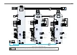
Figure 3-6 Typical system wiring diagram
WARNING
The drive unit has a fuse. Independent power-on without a DC soft charge unit is inhibited because such power-on will damage the drive unit.
Содержание MD810 Series
Страница 1: ...User Guide MD810 Series Standard Drive Multidrive System A04 Data code 19010518 User Guide...
Страница 37: ...2 Installation 36 External 24 V power supply Connect with the drive unit terminal Figure e Figure f Figure g...
Страница 38: ...2 Installation 37 Figure h Figure i Figure 2 7 HST 6004 HST 7004 DC soft charge unit installation...


