Appendix A Parameter Table
- 149 -
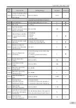
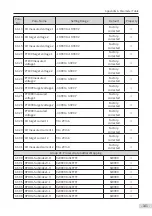
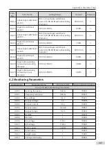
Para.
No.
Para. Name
Setting Range
Default
Property
B2-13
Linear taper switchover
point 3
B2-11 (Linear taper switchover
point 2) to B0-08 (Maximum winding
diameter)
250.0 mm
☆
B2-14 Taper of switchover
point 3
0.0% to 100.0%
80.0%
☆
B2-15 Linear taper switchover
point 4
B2-13 (Linear taper switchover
point 3) to B0-08 (Maximum winding
diameter)
300.0 mm
☆
B2-16 Taper of switchover
point 4
0.0% to 100.0%
70.0%
☆
B2-17
Linear taper switchover
point 5
B2-15 (Linear taper switchover
point 4) to B0-08 (Maximum winding
diameter)
400.0 mm
☆
B2-18 Taper of switchover
point 5
0.0% to 100.0%
50.0%
☆
B2-19
Taper corresponding
to maximum winding
diameter
0.0% to 100.0%
30.0%
☆
B2-20
Taper corresponding
to maximum reel
diameter
0.0% to 100.0%
30.0%
☆
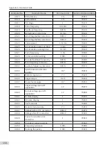
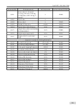
A.2 Monitoring Parameters
Parameter No.
Parameter Name
Minimum Unit
Communication Address
Group U0: Basic Monitoring Parameters
U0-00
Running frequency
0.01 Hz
7000H
U0-01
Frequency reference
0.01 Hz
7001H
U0-02
Bus voltage
0.1 V
7002H
U0-03
Output voltage
1 V
7003H
U0-04
Output Current
0.1 A
7004H
U0-05
Output power
0.1 kW
7005H
U0-06
Output torque
0.1%
7006H
U0-07
DI state
1
7007H
U0-08
DO state
1
7008H
U0-09
AI1 voltage
0.01 V
7009H
U0-10
AI2 voltage
0.01 V
700AH
U0-11
Motor speed
1 RPM
700BH
U0-12
Count value
1
700CH
U0-13
Length value
1
700DH
U0-14
Load speed display
1
700EH
Содержание MD810 Series
Страница 1: ...User Guide MD810 Series Standard Drive Multidrive System A04 Data code 19010518 User Guide...
Страница 37: ...2 Installation 36 External 24 V power supply Connect with the drive unit terminal Figure e Figure f Figure g...
Страница 38: ...2 Installation 37 Figure h Figure i Figure 2 7 HST 6004 HST 7004 DC soft charge unit installation...

