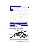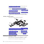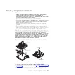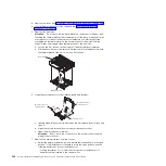
1. Read the safety information that begins on page vii and “Installation guidelines”
2. If the system-board tray is installed in a chassis, remove it (see “Removing the
system-board tray from a 2U chassis” on page 279).
3. Remove the system-board tray cover (see “Removing the system-board tray
4. If necessary, note the cable routing and connection locations; then, disconnect
the cables that connect the system-board tray to the chassis.
Attention:
v
Disengage all latches, release tabs or locks on cable connectors when you
disconnect all cables from the system board. Failing to release them before
removing the cables will damage the cable sockets on the system board.
The cable sockets on the system board are fragile. Any damage to the cable
sockets may require replacing the system board.
v
Failing to install or remove the cable with care may damage the connectors
on the system board. Any damage to the connectors may require replacing
the system board.
5. Remove the hard disk drives, if any are installed (see “Removing a
simple-swap hard disk drive” on page 293).
6. Remove the hard disk drive bracket and cable assembly.
7. Remove the simple-swap SAS/SATA drive cage, if one is installed (see
“Removing a simple-swap SAS/SATA drive cage” on page 299).
8. Remove the riser cards (see “Removing a PCIe riser-card assembly from the
system-board tray” on page 302) and dual-port network adapter (see
“Removing the optional dual-port network adapter” on page 321).
9. Remove the power-supply paddle card, if any are installed (see “Removing a
power-supply paddle card from the tray” on page 301).
10. Remove the DIMMs (see “Removing a memory module” on page 309).
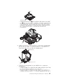
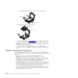
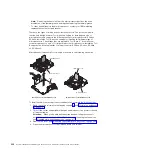
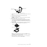
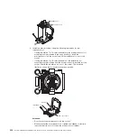
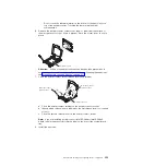
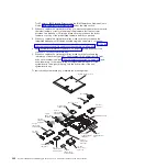
11. Remove the microprocessors and heat sinks (see “Removing a microprocessor
Notes:
a. Remove the socket covers from the microprocessor sockets on the new
system board and place them on the microprocessor sockets of the system
board you are removing.
b. Do not allow the thermal grease to come in contact with anything, and
keep each heat sink paired with its microprocessor for reinstallation.
Contact with any surface can compromise the thermal grease and the
microprocessor socket. A mismatch between the microprocessor and its
original heat sink can require the installation of a new heat sink.
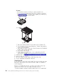
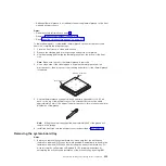
12. If you are instructed to return the system-board tray, follow all packaging
instructions, and use any packaging materials for shipping that are supplied to
you.
Note:
Remove the shipping brackets from the replacement system-board tray
and install them on the system-board tray you are returning.
Chapter 5. Removing and replacing server components
337
Содержание System x iDataPlex dx360 M4 7912
Страница 1: ...System x iDataPlex dx360 M4 Types 7912 and 7913 Problem Determination and Service Guide...
Страница 2: ......
Страница 3: ...System x iDataPlex dx360 M4 Types 7912 and 7913 Problem Determination and Service Guide...
Страница 22: ...4 System x iDataPlex dx360 M4 Types 7912 and 7913 Problem Determination and Service Guide...
Страница 278: ...260 System x iDataPlex dx360 M4 Types 7912 and 7913 Problem Determination and Service Guide...
Страница 292: ...274 System x iDataPlex dx360 M4 Types 7912 and 7913 Problem Determination and Service Guide...
Страница 392: ...374 System x iDataPlex dx360 M4 Types 7912 and 7913 Problem Determination and Service Guide...
Страница 399: ......
Страница 400: ...Part Number 46W8218 Printed in USA 1P P N 46W8218...

