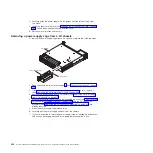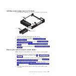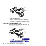
4. If a GPGPU enclosure is installed on the system-board tray, remove it (see
“Removing a GPGPU enclosure” on page 281); otherwise, remove the
system-board tray cover (see “Removing the system-board tray cover” on page
280).
5. Remove the PCI riser-card assembly (if installed) from PCI riser connector 2
(see “Removing a PCIe riser-card assembly from the system-board tray” on
page 302).
6. Remove the adapter filler panel on the front of the chassis (if it has not been
removed already).
7. Touch the static-protective package that contains the new adapter to any
unpainted metal surface on the server. Then, remove the adapter from the
package.
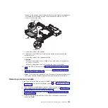
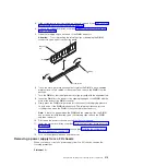
8. Align the adapter so that the port connectors on the adapter line up with the
pin and thumbscrew on the chassis; then, tilt and slide the adapter so the port
connectors on the adapter and the network adapter connector on the planar
are aligned.
9. Press the adapter firmly until the pin, and retention brackets engage the
adapter. Make sure the adapter is securely seated on the connector on the
planar.
Attention:
Make sure the port connectors on the adapter are aligned
properly with the chassis on the rear of the server. An incorrectly seated
adapter might cause damage to the system board or the adapter.
10. Fasten the captive screws on the network adapter.
11. Fasten the thumbscrew on the front of the chassis.
12. Reinstall the PCI riser-card assembly in PCI riser connector 2 if you have
removed it previously (see “Installing a PCI riser-card assembly on the
system-board tray” on page 303).
13. Install the system-board tray cover (see “Installing the system-board tray
14. Install the system-board tray in the chassis (see “Installing the system-board
tray in a 2U chassis” on page 279).
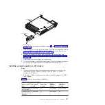
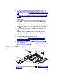
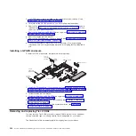
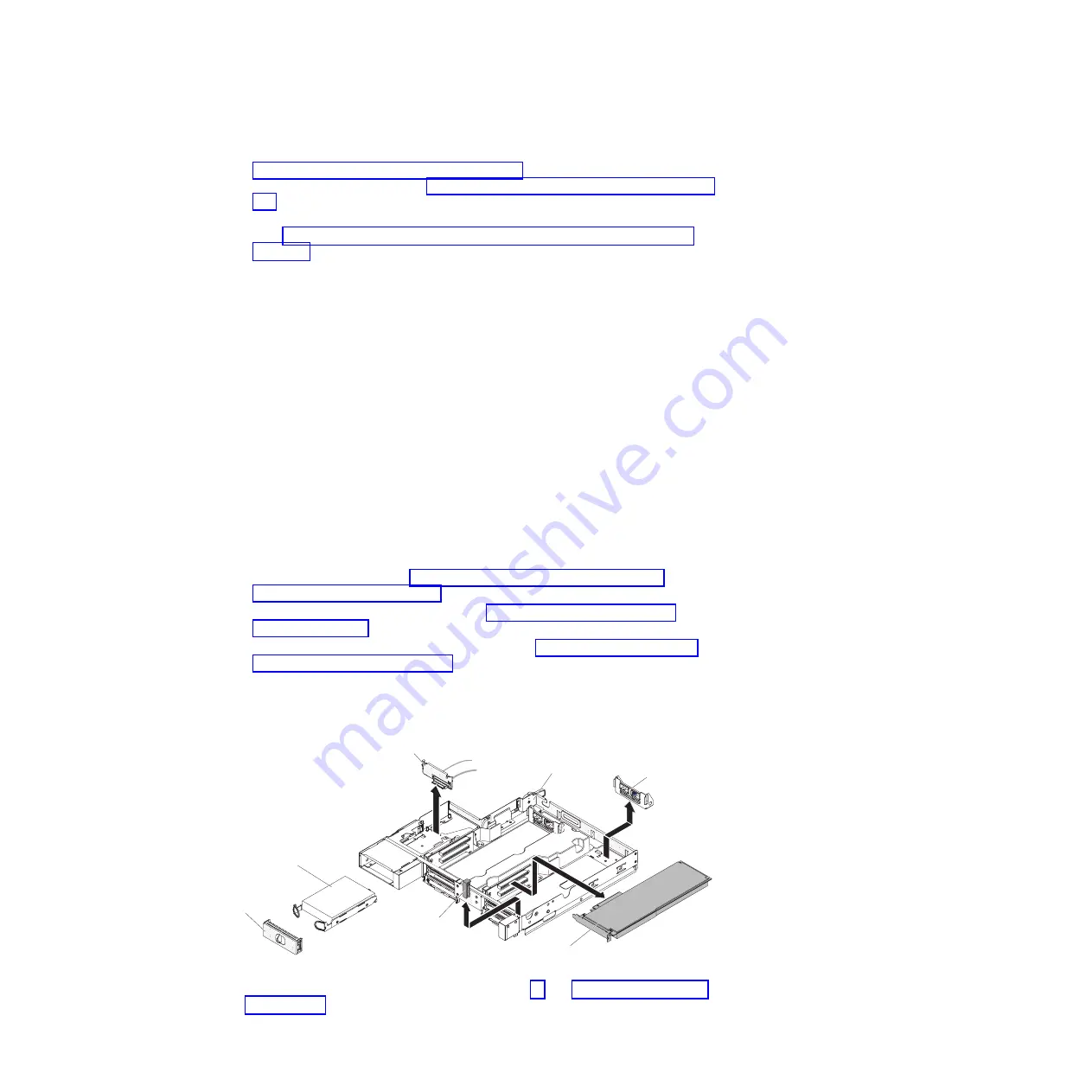
Removing a GPGPU enclosure
To remove a GPGPU enclosure, complete the following steps.
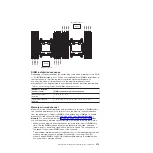
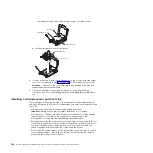
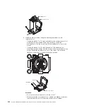
Retention bracket
Retention pin
Adapter
3.5-inch
simple-swap
backplate
3.5-inch
simple-swap
hard disk drive
3.5-inch
filler panel
GPGPU enclosure
1. Read the safety information that begins on page vii and “Installation guidelines”
Chapter 5. Removing and replacing server components
323
Содержание System x iDataPlex dx360 M4 7912
Страница 1: ...System x iDataPlex dx360 M4 Types 7912 and 7913 Problem Determination and Service Guide...
Страница 2: ......
Страница 3: ...System x iDataPlex dx360 M4 Types 7912 and 7913 Problem Determination and Service Guide...
Страница 22: ...4 System x iDataPlex dx360 M4 Types 7912 and 7913 Problem Determination and Service Guide...
Страница 278: ...260 System x iDataPlex dx360 M4 Types 7912 and 7913 Problem Determination and Service Guide...
Страница 292: ...274 System x iDataPlex dx360 M4 Types 7912 and 7913 Problem Determination and Service Guide...
Страница 392: ...374 System x iDataPlex dx360 M4 Types 7912 and 7913 Problem Determination and Service Guide...
Страница 399: ......
Страница 400: ...Part Number 46W8218 Printed in USA 1P P N 46W8218...

