v
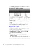
The following table shows an example of the maximum amount of memory that
you can install using ranked DIMMs:
Table 10. Maximum memory installation using ranked DIMMs
Number of DIMMs
DIMM type
DIMM size
Total memory
16
Single-rank UDIMMs
2 GB
32 GB
16
Single-rank RDIMMs
2 GB
32 GB
16
Single-rank RDIMMs
4 GB
64 GB
16
Dual-rank UDIMMs
4 GB
64 GB
16
Dual-rank RDIMMs
4 GB
64 GB
16
Dual-rank RDIMMs
8 GB
128 GB
16
Quad-rank LRDIMMs
32 GB
512 GB
v
The UDIMM option that is available for the server are 2 GB and 4 GB. The
server supports a minimum of 2 GB and a maximum of 64 GB of system memory
using UDIMMs.
v
The RDIMM options that are available for the server are 2 GB, 4 GB, and 8 GB.
The server supports a minimum of 2 GB and a maximum of 128 GB of system
memory using RDIMMs.
v
The LRDIMM option that is available for the server is 32 GB. The server supports
a minimum of 32 GB and a maximum of 512 GB of system memory using
LRDIMMs.
Note:
The amount of usable memory is reduced depending on the system
configuration. A certain amount of memory must be reserved for system
resources. To view the total amount of installed memory and the amount of
configured memory, run the Setup utility. For additional information, see
“Configuring the server” on page 342.
v
A minimum of one DIMM must be installed for each microprocessor. For
example, you must install a minimum of two DIMMs if the server has two
microprocessors installed. However, to improve system performance, install a
minimum of four DIMMs for each microprocessor.
v
DIMMs in the server must be the same type (RDIMM or UDIMM) to ensure that
the server will operate correctly.
v
When you install one quad-rank DIMM in a channel, install it in the DIMM
connector furthest away from the microprocessor.
Notes:
1. You can install DIMMs for microprocessor 2 as soon as you install
microprocessor 2; you do not have to wait until all of the DIMM slots for
microprocessor 1 are filled.
2. DIMM slots 9-16 are reserved for microprocessor 2; thus, DIMM slots 9-16 are
enabled when microprocessor 2 is installed.
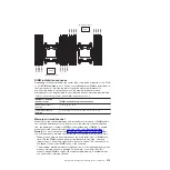
The following illustration shows the location of the DIMM connectors on the system
board.
312
System x iDataPlex dx360 M4 Types 7912 and 7913: Problem Determination and Service Guide
Содержание System x iDataPlex dx360 M4 7912
Страница 1: ...System x iDataPlex dx360 M4 Types 7912 and 7913 Problem Determination and Service Guide...
Страница 2: ......
Страница 3: ...System x iDataPlex dx360 M4 Types 7912 and 7913 Problem Determination and Service Guide...
Страница 22: ...4 System x iDataPlex dx360 M4 Types 7912 and 7913 Problem Determination and Service Guide...
Страница 278: ...260 System x iDataPlex dx360 M4 Types 7912 and 7913 Problem Determination and Service Guide...
Страница 292: ...274 System x iDataPlex dx360 M4 Types 7912 and 7913 Problem Determination and Service Guide...
Страница 392: ...374 System x iDataPlex dx360 M4 Types 7912 and 7913 Problem Determination and Service Guide...
Страница 399: ......
Страница 400: ...Part Number 46W8218 Printed in USA 1P P N 46W8218...

