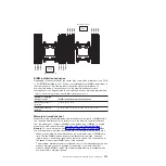
The following diagram lists the DIMM connectors on each memory channel.
DIMM 3
DIMM 9
DIMM 6
DIMM 12
DIMM 2
DIMM 8
DIMM 5
DIMM 11
DIMM 1
DIMM 7
DIMM 4
DIMM 10
Microprocessor 1
Channel
CPU1
DIMM 15
DIMM 14
DIMM 13
DIMM 16
Microprocessor 2
CPU2
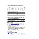
The following table shows the memory channel interface layout with the DIMM
installation sequence for memory mirrored channel:
Table 12. Memory channel interface layout
Memory channel
DIMM connector
Channel 0
7, 8, 15, 16
Channel 1
5, 6, 13, 14
Channel 2
1, 2, 9, 10
Channel 3
3, 4, 11, 12
The following table shows the installation sequence for memory-mirroring mode:
Table 13. Memory mirroring mode DIMM population sequence
Number of installed microprocessor
DIMM connector in pair
Microprocessor 1 (1 CPU only)
1, 3-> 6, 8-> 2, 4-> 5, 7
Microprocessor 1 and microprocessor 2
1, 3, 9, 11-> 6, 8, 14, 16-> 2, 4, 10,
12-> 5, 7, 13, 15
Memory rank sparing
The memory rank sparing feature disables the failed memory from the system
configuration and activates a rank sparing DIMM to replace the failed active DIMM.
You can enable either memory rank sparing or memory mirrored channel in the
Setup utility (see “Using the Setup utility” on page 345). When you use the memory
rank sparing feature, consider the following information:
v
The memory rank sparing feature is supported on server models with an Intel
Xeon
™
E5-2600 series microprocessor.
v
When you enable the memory rank sparing feature, you must install two or three
DIMMs on the same channel per microprocessor at a time. The first two DIMMs
must be in the same channel. The sparing DIMM must be identical or larger in
size, type, rank, and organization, but not in speed. The channels run at the
speed of the slowest DIMM in any of the channels.
v
The maximum available memory is reduced to two-thirds or one-half of the
installed memory when memory rank sparing mode is enabled.
Installing a DIMM
To install a DIMM, complete the following steps:
1. Read the safety information that begins on page vii and “Installation guidelines”
2. Turn off the server and peripheral devices and disconnect the power cords and
all external cables, if necessary.
314
System x iDataPlex dx360 M4 Types 7912 and 7913: Problem Determination and Service Guide
Содержание System x iDataPlex dx360 M4 7912
Страница 1: ...System x iDataPlex dx360 M4 Types 7912 and 7913 Problem Determination and Service Guide...
Страница 2: ......
Страница 3: ...System x iDataPlex dx360 M4 Types 7912 and 7913 Problem Determination and Service Guide...
Страница 22: ...4 System x iDataPlex dx360 M4 Types 7912 and 7913 Problem Determination and Service Guide...
Страница 278: ...260 System x iDataPlex dx360 M4 Types 7912 and 7913 Problem Determination and Service Guide...
Страница 292: ...274 System x iDataPlex dx360 M4 Types 7912 and 7913 Problem Determination and Service Guide...
Страница 392: ...374 System x iDataPlex dx360 M4 Types 7912 and 7913 Problem Determination and Service Guide...
Страница 399: ......
Страница 400: ...Part Number 46W8218 Printed in USA 1P P N 46W8218...

