Installation __________________________________________________________________________
RF-MCGARDPRO
Hubbell Power Systems, Inc.
–
RFL™
Products
July 1, 2022
©2022 Hubbell Incorporated
3-25
Additional interfaces can be added as required, and as space in the chassis allows. The 6U chassis
can house an additional 7 communication interfaces, for a total of 8. The 3U chassis can house
an additional 4 communication interfaces, for a total of 5. Both 3U and 6U chassis can have a
maximum of 2 T1/E1 modules installed.
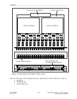
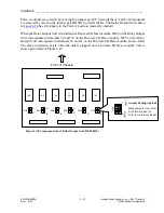
There are various types of Comms modules that can be mounted on the Comms I/O Base as
follows: Refer to
for the panel views of the Comms modules.
•
RS-232 Async Comms Unit (Auxiliary Channel Only)
•
RS-449, X.21, V.35 Comms Unit (Multiprotocol Module)
•
G.703 Comms Unit
•
T1/E1 100/120 Ohm Unit
•
E1 75 Ohm (BNC) Unit
(See Note below)
•
C37.94 Unit
•
Fiber Unit, 1300 nm LED
•
Fiber Unit, 1300 nm Laser
•
Fiber Unit, 1550 nm Laser
Note
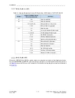
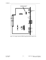
: On the E1 75 Ohm Unit, Jumpers J12 and J13 are used to ground the shield of the E1
coaxial connectors, when required. The default positions are:
•
J12 – U (RX port shield ungrounded)
•
J13 – G (TX port shield grounded)
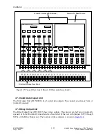
There are three types of I/O modules that can be mounted on the Digital Comms I/O Base as
follows:
•
Input Unit
•
SS Output Unit
•
Relay Output Unit
When no I/O module is selected at the time of ordering, systems will be produced with a Digital
Comms Base module without I/O (RF-500845). This module will not include a I/O terminal block
or provision for adding a I/O module.

