Digital Communications Interfaces ________________________________________________________
RF-MCGARDPRO
Hubbell Power Systems, Inc.
–
RFL™
Products
July 1, 2022
©2022 Hubbell Incorporated
7-3
•
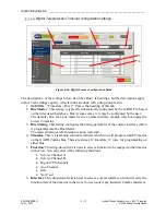
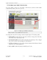
Comms Subsystem (Comms Bus). There are two 12 x 64 kbps internal comms buses
and the physical comms interface can be selected to use either of these two buses.
•
Clock mode. Each internal bus needs one Master timing source provided via a comms
interface.
•
Timing. Timing source can be selected to be internal or loop (external). If this is
configured for internal the module will provide the communications clock. If configured
for loop the module will rely on an external clock source, a T1/E1 multiplexer or
SONET/SDH system for example.
•
Framing. Defines the T1 or E1 framing protocol used. The protocols are:
o
T1:
SF - Super Frame
ESF - Extended Super Frame
o
E1:
CCS - Common Channel Signaling
•
Coding. Defines the T1 or E1 coding protocol used. The protocols are:
o
AMI: T1/E1. Alternate Mark Inversion format represents a digital 1 as a square
wave and a digital 0 as a straight line. AMI is a bipolar format, each pulse
alternates between positive and negative polarity. Consecutive pulses of the
same polarity constitute a Bi-polar violation (BPV) and the signal is no longer
valid.
o
B8ZS: T1. Bipolar with 8-Zero Substitution uses intentional Bi-polar violations
to break up long strings of zeros. Any string of eight consecutive zeros is
replaced with 2 intentional bi-polar violations before being transmitted.
o
HDB3: E1. High Density Bipolar of Order 3. An excessive string of consecutive
zeros (>3) is replaced by a special code containing deliberate Bipolar Violations
(BPV).
•
Line Build Out. Line build out on T1 and E1 interfaces adjusts the output characteristics
of the interface to match impedance characteristics of the cable. This is done by
selecting either the distance between the GARD Pro chassis and the communications
equipment, selecting a desired attenuation level in dB or matching the output impedance
for coaxial or twisted pair cables. Setting the line build out for the distance from the
GARD Pro chassis to the communications equipment will be sufficient for most
applications.
•
TX/RX Clock Polarity. Defines the clock polarity of the RS-449/X.21/V.35 comms
interface. This can be set for (TX/RX):
o
NORM / NORM
o
NORM / INVERT
o
INVERT / NORM
o
INVERT / INVERT


