


Digital Teleprotection __________________________________________________________________
RF-MCGARDPRO
Hubbell Power Systems, Inc.
–
RFL™
Products
July 1, 2022
©2022 Hubbell Incorporated
6-9
6.3.2 Digital Teleprotection Timeslot Configuration
Note
: Digital Teleprotection Timeslot configuration tabs are a duplicate of the Digital Comms
Timeslot configuration. Changing Timeslot configuration in the Digital Comms configuration
interface is reflected in the Digital Teleprotection Timeslot configuration. See section
Note
: Interfaces used for Aux channels are not configurable as Timeslot Interfaces or as Bus
Master.
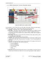
This page configures the GARD Digital Teleprotection Timeslots. There are two bus groups
available associated with Comms Bus 1 (“Bus 1”) and Comms Bus 2 (“Bus 2”). Each Bus has
its own tab. In each group, there are 12 “timeslots” which run at 64 kbps each. A timeslot must
have a function / interface combination to have valid programming. But it can also be empty.
Each comms bus has a “bus master” or timing master, which provides the timing to the bus.
There are several rules and programming requirements specific to handling how the master is
assigned and programmed.
Note
: “timeslots” and bus timing are independent of the system real-time clock and are not
related. Communications timing refers to synchronous communications where all transmitters
and receivers must have a single timing source.
Except for T1/E1, if a digital communications interface is configured for more than one
timeslot, it requires additional framing data, which increases the data rate of the interface by 64
kbps. Framing is enabled automatically when multiple timeslots are assigned to an interface.
Figure 6-7. Digital Teleprotection Timeslot Configuration screen


