Installation __________________________________________________________________________
RF-MCGARDPRO
Hubbell Power Systems, Inc.
–
RFL™
Products
July 1, 2022
©2022 Hubbell Incorporated
3-18
Grounding is accomplished by connecting a wire 6AWG or larger between this protective earth
stud and rack ground. The grounding wire should be kept as short and straight as possible, to
keep its resistance and inductance to a minimum.
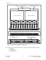
Before attempting to make power connections, make sure the HPS/RFL GARD Pro system
terminal is equipped with a power supply designed to operate at the available input supply
voltage. This can be determined by checking the power supply label on the exterior of the unit,
as shown in
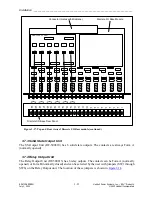
If an external power supply is being used, check the markings on the
external power supply. If the wrong voltage is connected to the power supply, component
damage will result.
3.6.4 Input Power Connections
WARNING!
Electric shock, equipment damage
Install individual double pole disconnects between the building or station battery supply and
HPS/RFL GARD Pro system power supply. This must be done for both the main and back-up
supply.
CAUTION
Damage to the power supply
Power supplies are
not
hot swappable. Switch off power at the appropriate power supply before
installing or removing power supplies from the HPS/RFL GARD Pro system chassis
After all other connections have been made to the HPS/RFL GARD Pro system, input power
connections can be made to the Power Supply I/O at the rear of the chassis.
Before proceeding to connect power to the HPS/RFL GARD Pro system ensure that the main and
redundant power switches on the rear of the unit are in the “OFF” position and that the power wires
to be installed are disconnected at their source.
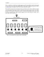
Make input power supply connections for all power supplies installed. Depending on the number
of power supplies installed the locations of the connections for each power supply are shown in
the following table:
Number Location at Front Terminal Block Label at Rear
1
Power Supply 1
Power Supply 1
1
Power Supply 2
Power Supply 2
2
Power Supply 1 and Power Supply 2
Input power connections can be either DC station battery voltage (24, 48, or 250VDC) or AC
voltage (125VAC or 220VAC), depending on which power supplies are installed in the chassis.
Station battery positive goes to the “+” terminal and station battery negative goes to the “-“
terminal. If AC input power is used, connections are made to the “+” and “-” terminals and the
polarity markings can be neglected.


