


Installation __________________________________________________________________________
RF-MCGARDPRO
Hubbell Power Systems, Inc.
–
RFL™
Products
July 1, 2022
©2022 Hubbell Incorporated
3-24
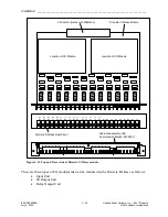
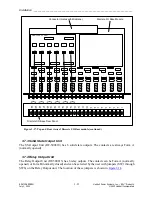
Connector (mates with Midplane)
Discrete I/O Base Module
1
2
3
4
5
6
7
8
9
10
11
12
13
14
15
16
17
18
19
20
21
22
23
24
Discrete I/O Base Rear Panel
GARD OUTPUT UNIT
{
{
{
{
{
{
SW1
SW2
SW3
SW4
SW5
SW6
K1
K2
K3
K4
K5
K6
A
B
A
A
A
B
B
B
B
B
A
A
Figure 3-19. Top and Rear view of Discrete I/O Base module with Output unit
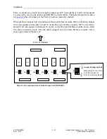
3.8
Digital Comms I/O Base Module and Digital Interfaces
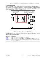
The function of the Comms I/O Base module (RF-500850) is to hold one Comms module and
one I/O module. The Comms module and the I/O module plug onto the Comms I/O Base using
an array of connector pins on the Comms I/O base which plug into mating connectors on the
Comms module and the I/O module. The location of the I/O module and the Comms module in
the Comms I/O Base is shown in
The communication interfaces are mounted from the rear of the chassis. The comms connectors
are located on the top half of the 6U chassis or on the right side of the 3U chassis. The remaining
half of the board can be equipped with a set of six inputs, solid state outputs or relay outputs.


