Digital Teleprotection __________________________________________________________________
RF-MCGARDPRO
Hubbell Power Systems, Inc.
–
RFL™
Products
July 1, 2022
©2022 Hubbell Incorporated
6-6
6.2.1 Digital Teleprotection Channels
The GARD Pro Digital Teleprotection System provides up to 32 functions over four channels, or
four 64 kbps time slots. Up to four channels are supported via the RS-449/X.21/V.35
(multiprotocol) interface provided on the Power Supply I/O and/or via any of the optional
communication interfaces. Each of the four 64 kbps channels provides 8 functions each, giving a
total of 32 functions in one digital teleprotection system. Additional teleprotection channels can
be added to the Base System. An optional G.703 interface may be used in place of the standard
interface.
Each Digital Comms module, including the Power supply I/O provides up to twelve, 64 kbps
channels. Except for G.703 which is 64k-only (one 64k channel)
The system has 4 Independent Teleprotection Channels named Channels 1-4 (64kbps each).
Each data message is 32 bits (500us). The bits for each message are structured as:
•
8 fu 6 CRC + 2 Ping + 8 Addr 4 Remote Service C 4 Framing
A valid trip must include 2 valid trip messages. Each valid message includes:
•
Valid CRC, valid frame & valid address
•
8-bit address. The address must match the programmed receive address of the
teleprotection channel.
6.3
Digital Teleprotection Configuration
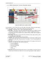
In the left menu, select “Configuration > Digital Teleprotection”. This provides a list of D-TPS
modules installed. Select the module needed. The general form is (Module 1 location) – TPS
with a specific example being “Slot 2 – TPS”. Each TPS module shows two tabs to configure.
•
General
•
Advanced
•
Timeslots - Bus 1 & Bus 2 tabs.
6.3.1 Digital Teleprotection Configuration
– General tab
This page allows the user to configure different parameters of the Digital Teleprotection module.
Each module has its own page and its own sidebar menu item. User can select between modules
by using the sidebar menu or by using the drop-down next to the tabs.
The menu item “Digital Teleprotection” and page are available/visible only when a teleprotection
module is installed somewhere in the chassis.
All four channels are shown for each teleprotection module, regardless of whether those channels
are currently mapped to a timeslot / communications interface.

