background image

System Configuration  __________________________________________________________________  

RF-MCGARDPRO 


    Hubbell Power Systems, Inc. 


RFL™ 

Products


July 1, 2022 


©2022 Hubbell Incorporated 

4-30 


Output Test 

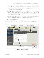
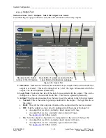
Menu location:  Test > Outputs.  Select the output to be tested.


The following web page is used to verify the correct function of the relay outputs. 


1

2

3

4

5

6

Represents the Output 

number of the I/O module

Description of outputs as entered on the 

Label Enable Configuration webpage 


Figure 4-30.  Output Test 

1.


TB#/State:  

Indicates the terminal block number of the output function and whether the 

output  is  activated.    This  can  be  thought  of  as  ‘after’  the  logic  bit  associated  with  the 
output.  The field is updated dynamically.


2.


Logic State:  

Indicates the state of the logic bit associated with the output.  This can be 

thought of as ‘before’ the terminal block state.  This field is updated dynamically. 

3.


Action: 

This drop-down menu allows the tester to set the outputs to the following modes: 


Normal:  

This is the normal operating condition for the output.  The logic bus drives 

the output. 


Hold:  

This will lock the output to the state of the output when the test is executed. 


Off:  

Sets the output to a low state (0), independent of the status of the logic bit.


An output that is set for a normally closed contact will close. 


An output that is set as a normally open contact will open. 
See 

Section 3.6

 for further details. 


On:  

Sets the output to a high state (1), independent of the status of the logic bit.


An output that is set for a normally closed contact will open. 


An output that is set as a normally open contact will close. 
See 

Section 3.6

 for further details. 

Содержание GARD Pro

Страница 1: ...ronic retrieval system in whole or in part by any means electronic or otherwise For permission contact customer service rflelect com Hubbell Power Systems Inc RFL Products 353 Powerville Road Boonton...

Страница 2: ...rect information contained in this manual HPS shall not have any liability resulting from the use of the information in this manual This manual does not purport to cover all details or variations in e...

Страница 3: ...er Connections 3 16 3 7 Discrete I O Modules Connections Pinouts 3 19 3 8 Digital Comms I O Base Module and Digital Interfaces 3 24 3 9 Current Limiter Option 3 32 3 10 System Boot Up Sequence 3 33 Sy...

Страница 4: ...l Communications Interfaces 7 1 7 1 Digital Communications Function 7 1 7 2 Configure Digital Comms Modules 7 2 7 3 Digital Communications Timeslot configuration 7 13 7 4 Service Channels 7 21 7 5 Dig...

Страница 5: ...21 Figure 2 18 Events Log SOE s 2 21 Figure 2 19 Push Button Menu 2 22 Figure 2 20 Test Menu 2 22 Figure 2 21 Inventory Menu 2 23 Figure 3 1 Mounting dimensions for the HPS RFL GARD Pro system chassis...

Страница 6: ...4 17 Dynamic Menu Feature 4 18 Figure 4 18 Settings General Information 4 19 Figure 4 19 Removing Input Output Module 4 20 Figure 4 20 Setting Jumpers on the Input Unit 4 20 Figure 4 21 Setting Switc...

Страница 7: ...ut 4 72 Figure 4 65 DNP Status Type 20 SOE Counters 4 73 Figure 4 66 DNP Type 20 PLC Counters 4 73 Figure 4 67 DNP Status Type 30 Analog Input 4 74 Figure 4 68 DNP Status 4 74 Figure 4 69 DNP Status T...

Страница 8: ...08 Line Board Block Diagram 5 64 Figure 5 43 Location of Jumpers on the Line board 5 66 Figure 5 44 Location of Jumpers on the RX Filter board 5 67 Figure 5 45 Location of Jumpers on the RX Filter boa...

Страница 9: ...guration 7 14 Figure 7 16 Digital Comms Configuration fields 7 20 Figure 7 17 Configuring Service channels 7 21 Figure 7 18 Service Channel example 7 23 Figure 7 19 Status pages 7 25 Figure 7 20 Statu...

Страница 10: ...n Off Block Transport Delay and Channel Spacing 5 5 Table 5 4 Compatibility Issues for PLC Module Software 5 5 Table 5 5 TB1 Terminal Assignments 5 8 Table 5 6 Transmitter State 5 10 Table 5 7 Receive...

Страница 11: ...tal Module Module Level Alarms 8 2 Table 8 2 Digital Teleprotection Communications Modules Module Level Alarms 8 3 Table 8 3 PLC Common PLC Troubleshooting Issues 8 5 Table 8 4 Settings for the PLC Di...

Страница 12: ...Pro System is a trademark of Hubbell Power Systems Inc Windows is a registered trademark of Microsoft Corporation Ethernet is a trademark of Xerox Corporation The trademark information listed above i...

Страница 13: ...ted on the other mounting bracket along with other customer information SO 170523 PO 02345210000 PN GARD3U476 SN 07420072 Sales order number Purchase order number Part number Serial number RH LH GARD5...

Страница 14: ...ons Modules and Discrete I O None T1 DB15 RJ48 T0 E1 DB15 RJ48 N0 E1 BNC 50 or 75 ohm E0 Multiprotocol RS 449 V 35 X 21 M0 Short Haul Fiber C37 94 820nm LED Mulitmode ST H0 Short Haul Fiber C37 94 820...

Страница 15: ...ules Select Ten with 6U and Four with 3U Occupied Slot Based On Front Module Selection Empty Digital Communications Modules and Discrete I O T1 DB15 RJ48 E1 DB15 RJ48 E1 BNC 50 or 75 ohm Multiprotocol...

Страница 16: ...to comply with these requirements Ground the Chassis The chassis must be grounded to reduce shock hazard and allow the equipment to perform properly Equipment supplied with three wire AC power cables...

Страница 17: ...oltage may exist Do not Substitute Parts or Modify Equipment Because of the danger of introducing additional hazards do not install substitute parts or make unauthorized modifications to the equipment...

Страница 18: ...with comms modules that have fiber optic emitter heads Fiber optic emitter heads use a laser light source that produces invisible radiation Fiber optic communication systems are inherently safe in no...

Страница 19: ...PROPER CAUTION MUST BE EXERCISED WHEN SERVICING THIS EQUIPMENT ALL TERMINALS ON THE REAR OF THIS UNIT MAY HAVE HIGH VOLTAGE This device complies with Part 15 of the FCC rules and regulations Operatio...

Страница 20: ...r the HPS RFL GARD Pro System Figure 2 1 The HPS RFL GARD Pro System World class easy to use Graphical User Interface GUI Use 6U chassis for up to 8 functions or 3U chassis for up to 2 functions Integ...

Страница 21: ...s PLC option Input Output mapping System Jumper Settings Figure 2 2 Supplied Drawings 2 3 User System Label The User System Label is a combination of identifying fields so each unit and GARD PRO has a...

Страница 22: ...on Number GPR03U0123 This unit is a 3U GARD PRO with the assigned number 0123 Chassis Serial Number 19101234 This number is the year 19 the week 10 and a 4 digit ID 1234 User System Label GPR03U0123_C...

Страница 23: ...0 3 8 Input Output Modules Input Module RF 500805 3 7 1 4 9 Solid State Output RF 500810 3 7 3 4 9 Relay Output RF 500815 3 7 4 4 9 Available Options Digital Teleprotection Modules RF 500410 5 RF 5004...

Страница 24: ...the unit 1 Display Module Slot 1 8 Functional Modules Slot 3 and 4 Single Main Controller Slot 2 Spare Power Supply No2 Power Supply No1 3U Midplane 5 System I O Module 2 Main Input Output Module 6 P...

Страница 25: ...ower Supply No2 Power Supply No1 Spare Controller Module Redundant Controller Module 1 Display Module Second I O Module 5 System I O Module 2 Input Output Modules 4 Power Line Carrier Analog Modules o...

Страница 26: ...D s and a TCP IP port for PC web browser connection The main user interface is a web server connected to a PC via the TCP IP port There is an optional front mounted TSD Touch Screen Display see 2 9 Th...

Страница 27: ...o particular order Extraction Tool RF Shield Mid Plane Connector Input Unit Relay Output Unit Carrier Board 24 Position I O Terminal Block Voltage Selection Jumpers Form A B Switches 1 24 Figure 2 7 B...

Страница 28: ...d the I O module plug onto the Comms I O Base using an array of connector pins on the Comms I O base which plug into mating connectors on the Comms module and the I O module The location of the I O mo...

Страница 29: ...has eight LEDs and five test points on its front edge for service use only The PLC Analog Module has two BNC connectors for connection to the power line interface a six pin terminal block for connect...

Страница 30: ...ow Figure 2 9 GPS Antenna Also located on the System I O Module is a six pin RS 485 terminal block for use with the DNP protocol The six pin connector is always installed but only used when DNP is ena...

Страница 31: ...18 19 3 14 16 17 15 13 11 12 9 10 7 8 5 6 4 2 1 V 35 X 21 RS 44 9 1PPS IRIG B GPS ET HE RNE T 5 RS 485 MODBUS DNP 6 2 3 1 4 SY STE MI O RS 232 500 420 50 0855 V 35 X 21 RS 44 9 24 23 22 21 17 19 20 1...

Страница 32: ...erface Slot 1 in 3U Slot 9 in 6U RF 500410 7 System Display Standard Digital Teleprotection w G 703 64kbps Interface RF 500500 Stand alone Digital Teleprotection Module Front Functional Module Slots S...

Страница 33: ...e same configuration however the LEDs are orientated vertically RESET NET PWR 2 Green indicates that power is applied to the RFL GARD Pro System Programmable reset button will reset the LED s as speci...

Страница 34: ...system All interaction with the HPS RFL GARD Pro system is through a standard web browser The web pages reside in the device no special application software is required on the PC Figure 2 13 Graphica...

Страница 35: ...ion Two GARD Controllers present in the chassis in their dedicated slots facilitate the redundant mode of operation Only 6U chassis offer two controller slots Redundant mode is not possible with a 3U...

Страница 36: ...e module is idling in full operational condition All drivers of its signals to the backplane Ethernet etc are disabled Besides the Controller no slave module channel module or functional module in the...

Страница 37: ...process starts immediately after power up or reset of the Controller and continues as long as the module remains inactive When manually forcing a switch between redundant controllers for example insta...

Страница 38: ..._____ RF MCGARDPRO Hubbell Power Systems Inc RFL Products July 1 2022 2022 Hubbell Incorporated 2 19 Figure 2 14 Chassis Configuration Status web page for 6U Chassis with Redundancy Figure 2 15 Chassi...

Страница 39: ...cape display if the HPS RFL GARD Pro system is mounted vertically in a rack The illustration below shows the TSD mounted in a GARD 3U chassis its mounting and operation is the same in a 6U chassis The...

Страница 40: ...GARD system individual modules will display information unique to that module STATUS SOE Push Buttons Test Inventory HOME Slot 4 PLC ON OFF Slot 8 PLC ON OFF I O Alarms LEDs 1 20 Virtual LEDs 21 40 S...

Страница 41: ...This TSD page lists the current Push Button Configuration OFF0 Breaker12 ON1 ON2 OFF2 Breaker22 OFF1 ON1 ON4 ON6 ON3 OFF3 OFF4 ON5 Reset Mod 12 Mod22 OFF5 OFF6 Description5 Description6 Description 7...

Страница 42: ...tion ____________________________________________________________________ RF MCGARDPRO Hubbell Power Systems Inc RFL Products July 1 2022 2022 Hubbell Incorporated 2 23 SOE Inventory Menu Figure 2 21...

Страница 43: ...make sure the equipment is not damaged 2 After the chassis is removed from the carton carefully examine all packing material to make sure no items of value are discarded 3 Make sure all modules are fu...

Страница 44: ...m equipment must be securely mounted following the instructions in the following paragraphs Use the procedure that suits your equipment individual chassis interconnected chassis installed in racks or...

Страница 45: ...enclosed cabinet with a swing out rack must be securely fastened to the floor This will prevent the cabinet from falling forward when the rack is moved outward 14 5 36 83 5 25 13 335 19 48 26 18 312...

Страница 46: ...quipment facing the front of the rack or cabinet 2 Remove all the screws securing the shipping rails to the equipment 3 Slide the equipment into the rack or cabinet 4 Install and tighten screws to all...

Страница 47: ...connections as required as shown below IRIG B timing connection 1 Pulse per second timing connection GPS antenna connection optional Ethernet connection for remote access RS 232 connections Management...

Страница 48: ...tion for local access The front Ethernet port provides access to perform the initial setup of HPS RFL GARD Pro system The built in DHCP server assigns an IP address in the 192 168 1 subnet With this a...

Страница 49: ...rfaces may be active for DNP use at the same time For example one DNP master can access the HPS RFL GARD Pro system through RS485 and up to two other DNP masters may access through the rear Ethernet p...

Страница 50: ...a third master through the RTU on RS 485 The three masters can be in the same or different networks 3 5 4 RS 232 connections Management port This port provides an IRIG B reference signal from the HPS...

Страница 51: ...s a timing pulse each second The shape of the pulse makes the signal more precise than one second and can be a few microseconds or better The internal clock provides the timings less than a second wit...

Страница 52: ...ecial application only IRIG B signal through rear RS 232 port Jumper Locations GPS Module Locating J 11 J 10 1 1 2 2 15 15 16 16 J 3 J12 IRIG NORM NORM IRIG J6 J9 J4 J 7 J 8 J 13 J 14 1 1 SPARES 1 2 1...

Страница 53: ...d J10 1 2 Must be open 3 4 For Un modulated IRIG B inputs 5 6 7 8 For Modulated IRIG B inputs 9 10 No IRIG B termination 11 12 50 Ohm IRIG B termination 13 14 600 Ohm IRIG B termination J11 1 2 IRIG B...

Страница 54: ...be installed J8 11 12 IN Must be installed 13 15 IN IRIG B AGC is bypassed J10 3 4 IN For Unmodulated IRIG B inputs 13 14 IN 600 Ohm IRIG B termination J11 1 2 IN IRIG B shield is grounded 5 6 IN Mus...

Страница 55: ...G B position This will allow IRIG B signals to be brought into the GARD through pin 4 and 6 on the RS 232 connector 3 Refer to the following figure for the location of Jumper J3 and J12 The System I O...

Страница 56: ...0 OHM TERM ISOLATED GROUNDED 50 OHM NONE 600 OHM Set jumper J12 and J3 to the IRIG B position RS 232 Figure 3 9 Jumper Location for IRIG B through Rear RS 232 Connector 3U Partial view of rear of 6U G...

Страница 57: ...2 Hubbell Incorporated 3 15 J7 1 2 15 16 1 2 J8 15 16 J10 1 2 16 15 J5 1 A B J4 J13 J14 SPARES TB1 NORM IRIG J12 NORM IRIG J3 REQ D UNMOD MOD 1 2 J11 15 16 NONE 50 OHM 600 OHM TERM NONE 50 OHM 600 OHM...

Страница 58: ...23 24 Typical terminal block with six inputs and six relay outputs Out 2 Out 1 Out 3 In 2 In 1 In 3 In 4 In 5 In 6 Out 4 Out 5 Out 6 Output Input Figure 3 12 Rear I O Terminal Block Connections Note...

Страница 59: ...on C NC NO C NC NO POWER SUPPLY 1 POWER SUPPLY 2 MAJOR MINOR SW1 SW2 I 0 I 0 Relay Contacts Input Power Figure 3 13 Relay Connections Power Supply I O WARNING Improper ground connections may result in...

Страница 60: ...Damage to the power supply Power supplies are not hot swappable Switch off power at the appropriate power supply before installing or removing power supplies from the HPS RFL GARD Pro system chassis A...

Страница 61: ...ed to operate at the available input supply voltage Is the polarity of the supply power correct If installed in an enclosed cabinet is the unit ventilated correctly Power connections may now be made t...

Страница 62: ...1 0 Connector mates with Midplane Discrete I O Base Module Location of I O Module Location of I O Module 1 2 3 4 5 6 7 8 9 10 11 12 13 14 15 16 17 18 19 20 21 22 23 24 Discrete I O Base Rear Panel Alt...

Страница 63: ...unit is installed in a Discrete I O Base module J12 on the Input Unit corresponds to terminals 23 and 24 on the Discrete I O Base module J11 on the Input Unit corresponds to terminals 22 and 21 on th...

Страница 64: ...nel J12 J11 J10 J9 J8 J7 GARD INPUT UNIT Figure 3 17 Top and Rear views of Discrete I O Base module continued 3 7 3 Solid State Output Unit The SS Output Unit RF 500810 has 6 solid state outputs The c...

Страница 65: ...Relay Output Unit is installed in a Discrete I O Base module SW6 on the Relay Output Unit corresponds to terminals 24 and 23 on the Discrete I O Base module SW5 on the Relay Output Unit corresponds t...

Страница 66: ...Base Module and Digital Interfaces The function of the Comms I O Base module RF 500850 is to hold one Comms module and one I O module The Comms module and the I O module plug onto the Comms I O Base u...

Страница 67: ...e Comms modules RS 232 Async Comms Unit Auxiliary Channel Only RS 449 X 21 V 35 Comms Unit Multiprotocol Module G 703 Comms Unit T1 E1 100 120 Ohm Unit E1 75 Ohm BNC Unit See Note below C37 94 Unit Fi...

Страница 68: ...of I O Module Location of Digital Comms Module Connector mates with Midplane Comms I O Base Module Comms I O Base Rear Panel 13 15 14 16 17 18 19 20 21 22 23 24 Alternate assembly with Commpression Bl...

Страница 69: ...500890 1 1550nm 2mw Laser Direct Fiber X 21 V 35 500855 500860 J2 T1 E1 J1 500865 500870 E1 IN OUT C37 94 Rx Tx 500875 1300nm LED RX TX 500880 1300nm LASER RX TX 500885 AVOID EXPOSURE INVISIBLE LASER...

Страница 70: ...0nm 2mw LASER RF 500890 1 TX and RX Type ST RS 232 Async RF 500945 D sub 9 female one per channel 3 8 1 4 WARNING Your GARD Pro terminal may be equipped with comms modules that have fiber optic emitte...

Страница 71: ...pment Chassis Ground 1 RD A Receive Data A SD A Send Data A 2 3 4 6 7 8 11 12 13 RT B Receive Timing B 14 18 20 21 22 SD B Send Data B RD B Receive Data B RT A Receive Timing A Not Used 9 10 16 15 5 N...

Страница 72: ...in outs are shown below The same applies for the stand alone G 703 module interface 1 2 4 3 5 6 7 8 9 12 13 10 11 14 15 Chassis GND SD A Not Used RD A Not Used SD B Not Used RD B Not Used Figure 3 23...

Страница 73: ...nections The RS 232 Async Module uses a DB 9 Female Connector the pin outs are shown below 1 DB 9 Female RS 232 2 3 4 5 6 7 8 9 CD Carrier Detect RX Data TX Data DTR Data Terminal Ready Signal Ground...

Страница 74: ...on the inside of the chassis When viewed from the rear locate it by the following 3U chassis on the left hand side of the frame next to the I O System Module 6U chassis on the right hand frame below...

Страница 75: ...urpose unlit Red Amber Green DS 1 System Status Flashing Red is the initial boot sequence Booting continues Solid green means the boot Complete DS 2 Ethernet ports No cable NA Front port is connected...

Страница 76: ...an IP Address on the same subnet 192 168 1 x as described below The front port has no default gateway configured so it is not routable This is done for security purposes GA RD PRO RFL GARD Pro System...

Страница 77: ...ng the Windows 7 operating system Remember that operating systems are subject to updates and can vary slightly 4 2 Configuring a PC Using DHCP and Static IP 4 2 1 Configuring a PC using DHCP 1 Click o...

Страница 78: ..._________________________ RF MCGARDPRO Hubbell Power Systems Inc RFL Products July 1 2022 2022 Hubbell Incorporated 4 3 3 Click on Properties Figure 4 4 Properties 4 Highlight Internet Protocol Versio...

Страница 79: ...ically 6 Verify that DHCP is enabled and that the IP address given starts with 192 168 You can now logon to the HPS RFL GARD Pro system and access the built in web server 4 2 2 Configuring a PC using...

Страница 80: ...GARD Pro system for maintenance enter 192 168 1 1 in the address bar Following are instructions on logging onto the HPS RFL GARD Pro system web server 4 3 First Time Login to the HPS RFL GARD Pro Syst...

Страница 81: ...graphical representation of the HPS RFL GARD Pro system chassis is displayed in the main section of the web page You can toggle between the front and rear of the chassis clicking on individual modules...

Страница 82: ...administrator web page Up to 11 users including the Admin can be added by the administrator with individual access levels Setting Access Levels Administration When creating a new user the admin assign...

Страница 83: ...will allow various security settings to be activated or set such as login fail alarms and login lockout time Remember to click Save after changes are made After 5 unsuccessful login attempts lockout...

Страница 84: ...D PLC Pro Click to download and save the records to a local PC Click to delete the records erase them from the physical memory Figure 4 12 Access Log 4 4 File Operations Files may be sent from a PC to...

Страница 85: ...in one step System Logic Database TXT This file defines the web pages that configure the system logic It must be loaded prior to a new logic EDN loading System Logic EDN This file contains the system...

Страница 86: ...or the PLC module All three files are included in the PLC Firmware Software zip file They are all needed when the module is updated PLC Processor Software S19 PLC DSP Software S19 PLC Forth Software S...

Страница 87: ...ontains HPS RFL GARD Pro system layout and application drawings specific to each customer System Manual PDF This is the System Manual for the HPS RFL GARD Pro system It may be saved to a PC and viewed...

Страница 88: ...45 electrical or optical Ethernet port Field upgrades to the HPS RFL GARD Pro system are normally done utilizing the on board secure FTP SCP Web Server Note Field upgrades must be done through the fr...

Страница 89: ...available only for the rear port The front port must be configured for at least one protocol 3 HTTPS Certificate Key Pair In order to perform the security tasks involved the HPS RFL GARD Pro system ne...

Страница 90: ...tification Authority Store click on Next g Click on Finish Your browser will now trust all HPS RFL GARD Pro system web servers that are using HPS RFL s self signed certificate To prevent more warning...

Страница 91: ...hen asked what to do click on Save c Click on Tools Options In the Advanced Section select the Encryption tab d Click on View Certificates Firefox s Certificate Manager should appear e Click on the Au...

Страница 92: ...HPS RFL GARD Pro system chassis is provisioned can be accessed at any time from the main menu by clicking the Download button Menu location System Management Inventory Version Info Click to download...

Страница 93: ...listing with the next to it in this example will reveal the type of PLC modules installed in the HPS RFL GARD Pro system with their slot location You can then select the module to be configured Note T...

Страница 94: ...utside of the acceptable range with an error message as shown Error message Figure 4 18 Settings General Information Remember to save any changes that are made before exiting the web page 4 9 Input Ou...

Страница 95: ...sition and that power is disconnected at its source To remove the Input Output Module remove the two screws shown above Screw in the extraction tool where shown and using the tool gently slide the mod...

Страница 96: ...21 Setting Switches on the Relay Output Unit 4 9 4 Input Output Module Status Configuration and Test Solid state outputs relay outputs and input modules are equipped in sets of 6 with 2 modules on ea...

Страница 97: ...lowing web page shows the status of all I O cards in the HPS RFL GARD Pro system It is updated dynamically Type and location of card with its alarm status Description of inputs and outputs as programm...

Страница 98: ...iguration Menu location Configuration Inputs General The example web page below shows a typical label description list for Input 1 through 6 on the I O module Once all the fields have been filled in c...

Страница 99: ...ed to different points in the logic Input mapping choices are set up in the system logic The system logic provides a series of choices for mapping physical inputs to various points programmed in the s...

Страница 100: ...ed 4 25 Input Advanced Configuration Menu location Configuration Inputs Advanced The following setting should not be changed by the user Advanced tab See below Figure 4 25 Inputs Advanced Configuratio...

Страница 101: ...terminals This can be thought of as before the logic bit associated with the input This field is updated dynamically 2 Logic State Indicates the state of the logic bit associated with the input This...

Страница 102: ...input functions to normal operation Normal operation will place the state of the input onto the logic bus This function will be used to return the module to normal operating conditions after performin...

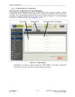
Страница 103: ...ed below the web page example Output mapping choices are set up in the system logic The system logic provides a series of choices for mapping various points programmed in the system logic to physical...

Страница 104: ...enu location Configuration Outputs Advanced CAUTION Inaccurate settings could cause service disruption The following setting should not be changed by the user Advanced tab See Logic Start Bit below Fi...

Страница 105: ...Logic State Indicates the state of the logic bit associated with the output This can be thought of as before the terminal block state This field is updated dynamically 3 Action This drop down menu all...

Страница 106: ...nction After the users press the Execute Action button the column indicates the mode that the function has changed to The lettering of the field will change to orange for any function that is not in n...

Страница 107: ...s are normally factory set but can be customized by the user through the GUI An example status screen is shown below followed by details on configuring the LEDs 4 10 1 LED Status Menu location Status...

Страница 108: ...anent A confirmation window will appear at the bottom right of the web page Note Virtual LED s are provided for viewing on the optional touch screen display Set the global LED label first by typing di...

Страница 109: ...ion The modules in the HPS RFL GARD Pro system continually perform self diagnostics For different conditions a module may issue either a major or minor alarm An example status screen is shown below fo...

Страница 110: ...t no bits are being driven by more than one source CAUTION This is a serious alarm contact HPS RFL for assistance 5 Comm Bus Error 1 and 2 An un configured COMMS bus will cause the alarm to go active...

Страница 111: ...ing of the major alarm indication from 0 to 30 seconds in 125ms increments 3 Minor Alarm Pickup Delay Once an abnormal condition is detected as programmed in the alarm configurations below the pickup...

Страница 112: ...SOE log is stored in the GARD in non volatile RAM Currently 2 048 events can be stored in the HPS RFL GARD Pro system database 4 12 1 Retrieving SOE Records Menu location Status SOE Records The follow...

Страница 113: ...d SOE will display below the scroll bar 5 Trigger Label The description of the SOE trigger as programed in the configuration web page 6 Status When the trigger changes to this state it generates the S...

Страница 114: ...ple clicking the symbol next to SOE record 1 will display the details page for record 1 This contains the state of all currently enabled SOE triggers at the instant the record was generated There is a...

Страница 115: ...Records Details Logic Bits Menu location Status SOE Logic Labels This web page shows the state of all system logic bits at the instant the SOE record was generated Mostly used by HPS RFL Service for e...

Страница 116: ...ds Details Logic Table Menu location Status SOE Details Logic Table This web page contains the same data as the logic bit list but presents it in table format Mostly used by HPS RFL Service for event...

Страница 117: ...enabled triggers The count can be reset by clicking the Reset button Menu location Status SOE Counters 1 2 3 4 Figure 4 39 SOE Counters 1 Trigger Number The trigger number column identifies the trigge...

Страница 118: ...tifies the trigger number used in the custom logic file 2 Trigger Label User definable label for each of the 191 triggers Change this field by changing the text and selecting Save once all the changes...

Страница 119: ...FL Products July 1 2022 2022 Hubbell Incorporated 4 44 page example various logic options can be enabled or disabled or set such as polarity and shift direction Go to Section 4 9 4 3 for Input Mapping...

Страница 120: ...ell Incorporated 4 45 4 13 2 Logic Timers Menu location Configuration Logic Logic Timers The available timers are dependent on the system logic files loaded into the HPS RFL GARD Pro system Timer sett...

Страница 121: ...6 7 Time since last power cycle or reboot 8 9 Figure 4 43 System Configuration Ethernet Labels 1 Active Port Displays which of the two Ethernet ports front or back is active 2 Rear IP Address Displays...

Страница 122: ...mber unique to an assembled chassis The Serial number can also be found on the side of the chassis User changeable in case of controller hardware being replaced 4 14 2 System Settings Clock Menu locat...

Страница 123: ...ps one pulse per second 4 15 Advanced Settings The following web pages are normally used for factory programming and troubleshooting only CAUTION Improper settings can cause system outage Only advance...

Страница 124: ...an be scrolled down through values from 2 to 63 There are two tabs one for HMI In and one for HMI Out The HMI In web page is shown below and the HMI Out page is similar Note The first two bits are res...

Страница 125: ...pull down menu on your PC select Settings Advanced Touch Screen Display 1 2 Figure 4 47 Navigate to Touch Screen Display Settings 1 Select Advanced to open the item 2 Select the Touch Screen Display...

Страница 126: ...tems Inc RFL Products July 1 2022 2022 Hubbell Incorporated 4 51 high to display the required screen bits 2 63 are available bits 0 and 1 are reserved To designate the wake up bit 1 Set the bit in the...

Страница 127: ...e Up to 8 Push Buttons can be configured Click Save after configuring the web page Sets the title of the buttons that will be seen on the TSD 15 Character Limit Selects the number of HMI In Bits that...

Страница 128: ...he appearance of the On button showing the text and the color chosen Display only Off Text The text desired for the display of the Off value 1 4 character string Off Color The color desired for the di...

Страница 129: ...ot configured i e Some or No Buttons are enabled the TSD will automatically display a Blank Screen or a Blank Button as Shown below OFF0 Breaker 12 ON 1 ON 2 OFF2 ON 4 ON 6 OFF4 ON 5 Reset Mod 12 OFF5...

Страница 130: ...to the interface data rate The menu item and page are available visible only when any digital comms module is installed in the chassis or when a display module is installed which is equipped with Dig...

Страница 131: ...s 2 less frequently and Class 3 even less frequently When a Class 1 2 or 3 poll is executed the slave device only returns those values which have changed state since the last poll A Class 0 poll retur...

Страница 132: ...Trip 2 Rx Rx Alarm Reflected Power Alarm n a 32 bit Binary 20 1 22 1 Rollover at 2554 PLC On Off Analog Values Tx Power Rx Level Reflected Power SNR dBm dB dB 32 bit floating point 30 1 32 1 Counters...

Страница 133: ...not stored in NVRAM it must be enabled by the DNP Master each time the GARD Pro is power cycled DNP3 Features The HPS RFL GARD Pro system provides the following features to aid managing the system 4...

Страница 134: ...t n 100 0 63 64 total o Rear n 100 64 99 Within the rear Top Right 64 81 18 total Bottom Left 72 99 18 total 4 16 1 2 4 Data Point Index auto assign rules In auto implementation the data point index i...

Страница 135: ...MCGARDPRO Hubbell Power Systems Inc RFL Products July 1 2022 2022 Hubbell Incorporated 4 60 4 16 2 DNP Configuration DNP General Configuration page Configuration DNP General This screen allows the us...

Страница 136: ...ield is disabled if TCP IP Master 1 is set to OFF 2000 65535 increment 1 20000 TCP IP Master 2 Allows the HPS RFL GARD Pro system DNP slave to communicate to a DNP master which is defined by the IP ad...

Страница 137: ...30 Type 1 Binary Input Configuration DNP Type 1 Binary Input This page lists any DNP Type 1 Binary Input points available for reporting System Logic HMI Outputs and SOE Triggers are always available...

Страница 138: ...ill always have parameter of 60 This field allows the user to assign connections between DNP points and their index numbers back to the HPS RFL GARD Pro system and logic System functional module param...

Страница 139: ...abled for recording in the Config SOE page are displayed in this page This page lists any DNP Type 20 Counter points available for reporting System Logic SOE Trigger Counters are always available Addi...

Страница 140: ...ell Power Systems Inc RFL Products July 1 2022 2022 Hubbell Incorporated 4 65 cannot be disabled for SOE recording until it has been disabled for DNP This is to ensure the integrity of the DNP point l...

Страница 141: ..._______________ RF MCGARDPRO Hubbell Power Systems Inc RFL Products July 1 2022 2022 Hubbell Incorporated 4 66 The remaining tabs configure any points available as supported by DNP capable modules suc...

Страница 142: ...July 1 2022 2022 Hubbell Incorporated 4 67 Type 30 Analog Configuration DNP Type 30 Analog This page lists any DNP Type 30 Analog points available for reporting This option is only available when supp...

Страница 143: ...will be reported at the next poll or generating an unsolicited message if configured The units used for the deadband setting depend on the measurement type For example Reflected Power is measured in p...

Страница 144: ...cts July 1 2022 2022 Hubbell Incorporated 4 69 4 16 3 DNP Status Webpages General tab Status DNP General This page shows general status of the DNP masters There is also an option to download a DNP Pro...

Страница 145: ...TCP IP Master 1 TCP IP Master 2 Displays the status of the HPS RFL GARD Pro system DNP reporting to TCP IP Master 2 Based on the setting in the Config DNP General page Disabled gray outline Enabled g...

Страница 146: ...e displayed on this page Figure 4 62 DNP Status Point List Field descriptions for DNP status Points from different sources are organized on separate tabs The Value field is updated dynamically If an o...

Страница 147: ...___ RF MCGARDPRO Hubbell Power Systems Inc RFL Products July 1 2022 2022 Hubbell Incorporated 4 72 Type 1 Binary Input Status DNP Type 1 Binary Input Figure 4 63 DNP Status Type 1 Binary Input Type 10...

Страница 148: ...__________________________________ RF MCGARDPRO Hubbell Power Systems Inc RFL Products July 1 2022 2022 Hubbell Incorporated 4 73 Type 20 Counter Status DNP Type 20 Counter Figure 4 65 DNP Status Type...

Страница 149: ..._________ RF MCGARDPRO Hubbell Power Systems Inc RFL Products July 1 2022 2022 Hubbell Incorporated 4 74 Type 30 Analog Input Status DNP Type 30 Analog Input Figure 4 67 DNP Status Type 30 Analog Inpu...

Страница 150: ...Home Status DNP The touch screen display will have status only display of DNP points The Point List is static it is assumed that no changes will be made to the DNP point list when viewing the list on...

Страница 151: ...rnet port These messages are triggered by changes in the HMI output bits as defined by the HPS RFL GARD Pro system logic In addition SNMP v3 GET functionality is supported allowing read access to the...

Страница 152: ...e The HMI OUT bit label The RTC based time stamp The User System Labels as set in the System Configuration page They are default under the names shown but can be labeled at the user s discretion Chass...

Страница 153: ...lt password to a unique value Change the password using the following steps 1 Navigate to the password change screen System Management Users Administration Figure 4 71 System Management Passwords Caut...

Страница 154: ...for editing whether the particular receiver is enabled or not Table 4 11 SNMP Configuration webpage fields Name Description Value The number of the trap receiver Read only value Community Provides a m...

Страница 155: ...e following table provides the SNMP Trap MIB contents provided with each generated trap message Table 4 12 SNMP Trap MIB contents MIB Field Description Object Identifier IMPORTS OBJECT TYPE MODULE IDE...

Страница 156: ...d tone is located at a fixed deviation below or above the channel center frequency At the occurrence of a trip the tone shifts to the opposite side of the channel center frequency In 3F operation a gu...

Страница 157: ...ible Bidirectional Channel Spacing Nominal Receive Bandwidth 200 Hz TX Frequency Shift 100 Hz 12 0 13 0 ms 500 Hz 1000 Hz Nominal Receive Bandwidth 500 Hz TX Frequency Shift 250 Hz 8 0 ms 1250 Hz 2500...

Страница 158: ...CGARDPRO Hubbell Power Systems Inc RFL Products July 1 2022 2022 Hubbell Incorporated 5 3 The example illustration on the following page shows the channel spacing in FSK mode for a 200 Hz receive band...

Страница 159: ...Normal Mode Otherwise the Remote responds in Normal Mode In Normal Mode the Remote responds by transmitting a pre defined sequence of On Off states called the Acknowledgement Code to the Master Four...

Страница 160: ...ic versions need to agree Beginning in October 2011 new PLC software indicated as V17 was released to improve the functionality of the unit Although these changes are transparent to the end user certa...

Страница 161: ...hole Chassis Configuration file can be determined by its file name See the example below taking note of the 17 identification after the revision letter Logic Filename GARD3U175_00146_001_A17 EDN TXT D...

Страница 162: ...Pro system PLC Module set is a Static Sensitive Device Persons working on this equipment must observe Electro Static Discharge ESD precautions As a minimum you must use anti static devices such as wr...

Страница 163: ...ignation Function TB1 1 15Vdc from external supply when required TB1 2 15Vdc from external supply when required TB1 3 Ground TB1 4 Carrier Level Indicator TB1 5 Not Used TB1 6 Ground To observe the Ca...

Страница 164: ...is required instructions are given in Section 5 5 5 1 5 4 PLC Module User Interface The web pages required for status display configuration calibration and test of the PLC module have been divided bet...

Страница 165: ...smit level falls below 28 5dBm 5 Reflected Power Records the reflected power as a percent 6 Reflected Power Level Reports the reflected power level as follows Excess Reflected Power or No Alarm 7 Curr...

Страница 166: ...ount Indicates the RX alarm count Counters Transmitter 17 Trip 1 Key Count Indicates the TX Key1 count 18 Trip 2 Key Count Indicates the TX Key2 count 19 Reflected Power Alarm Indicates the RPM fail a...

Страница 167: ...increments of 2 3 TX Guard Level Sets the transmit guard level The selections are 1W 3W or 10W 4 TX Trip Level Sets the transmit trip level The selections are 1W 3W or 10W 5 TX Trip 1 Shift Direction...

Страница 168: ...d be set to 0 5ms The time can be reduced for faster trips or lengthened for more security Can be set from 0 10ms in increments of 0 125ms RX Alarm Settings 10 Low Signal Level Alarm Sets the RX signa...

Страница 169: ...ntial in signal level between guard and trip frequencies required to declare a change of state Should be set to 15dB for proper operation The range is from 0dB to 100dB in 1dB increments 2 RX AGC Setp...

Страница 170: ...d but works the same Note The Guard RX Threshold setting became available with PLC firmware v24 Previous versions of firmware do not have this setting available CAUTION Changing the following bit rang...

Страница 171: ...0 Receiver Configuration PLC General Receiver Enable ON ON ON ON Configuration PLC General RX Center Frequency Configuration PLC General RX Bandwidth 200 Hz 500 Hz 500 Hz 500 Hz Configuration PLC Gene...

Страница 172: ...e Trip Enable Enable Enable Enable Configuration Logic Options Unblock On Low Level Alarm Disable Disable Enable Enable Configuration Logic Options Unblock On SNR Alarm Disable Disable Disable Disable...

Страница 173: ...xtend 0 5 0 5 ms 0 5 0 5 ms 0 5 0 5 ms 0 5 0 5 ms Configuration Logic Timers Counter 4 Delay Extend 0 5 0 5 ms 0 5 0 5 ms 0 5 0 5 ms 0 5 0 5 ms Configuration Logic Timers Counter 5 Delay Extend 0 5 0...

Страница 174: ...Activate Click to activate a change in the carrier state The following confirmation window will display Click Send Command an additional confirmation window will briefly display to indicate either su...

Страница 175: ...Status Menu location Status PLC 1 2 3 4 5 6 7 8 9 10 11 12 13 14 15 16 18 19 20 21 22 17 Figure 5 10 On Off Status Transmitter 1 Transmitter State Indicates the transmitter state as follows Block TX...

Страница 176: ...dicates the receive state as follows Block RX or No Carrier Received 11 RX Power Level Reports the RX level in dB relative to the normal RX level set during commissioning or Alarm 12 SNR Reports the S...

Страница 177: ...e click the Save button at the bottom right of the web page to make the settings permanent 1 2 3 4 5 7 8 9 11 13 12 10 6 Figure 5 11 On Off Configuration Transmitter 1 TX Block Frequency Sets the TX b...

Страница 178: ...to over trip for an external fault condition Start Stop Logic 10 Start Logic Sets the polarity for the Stop 1 and Stop 2 input contacts Can be set to Normal or Inverted When set to Normal the contact...

Страница 179: ...al in signal level between guard and trip frequencies required to declare a change of state Should be set to 15dB for proper operation The range is from 0dB to 100dB in 1dB increments 2 RX AGC Setpoin...

Страница 180: ...ecommended On Off Settings User Interface Web Page Path Setting Name Direct Comparison Blocking DCB Configuration PLC General Module Enable ON Transmitter Configuration PLC General TX Block Frequency...

Страница 181: ...ns Tx Fail Alarm Output Polarity Normal Logic Timers Configuration Logic Timers Checkback TIP Delay Extend 0 3000 ms Configuration Logic Timers Checkback Fail Delay Extend 100 100 ms Configuration Log...

Страница 182: ...other end set to Remote or both ends must be set to Disabled if the checkback feature is not being used 1 2 3 4 5 Checkback tab Function Buttons 6 Figure 5 13 On Off Configuration Checkback 1 Max Dela...

Страница 183: ...see 5 4 2 2 5 4 2 5 1 Recommended Checkback Settings Two Terminal RFL recommends the following settings for most standard PLC Checkback Two Terminal line testing operations Following the table below a...

Страница 184: ...8 TX Level Low Low Configuration PLC Checkback Remote Checkback Initiate 16 16 5 4 2 5 2 Recommended Checkback Settings Three Terminal RFL recommends the following settings for most standard PLC Chec...

Страница 185: ...f Off Off Configuration PLC Checkback Test 5 TX Level Low Low Low Configuration PLC Checkback Test 6 Command Off Off Off User Interface Web Page Path Setting Name Station A Station B Station C Configu...

Страница 186: ...request a hard carrier response The code can be sent using the following test page Selections are 1 16 or Off Hard Carrier Response 2 Code A low or high power response is sent if the selected code is...

Страница 187: ...ier Response Code High 14 12 Configuration PLC HardCarrier Response Time 30 s 30 s 5 4 2 6 2 Recommended Hard Carrier Settings Three Terminal RFL recommends the following settings for most standard PL...

Страница 188: ...minor alarm This reminds the user that the PLC is not in its normal state Note Remember to always put the carrier back into the normal state before leaving the unit Menu location Test PLC 1 3 2 4 5 6...

Страница 189: ...hard carrier request to the far end The selections are 1 to 4 or none Once selected click Send 8 PLC Module Logic Bus Outputs Enables or disables the Logic Bus Outputs Once a change is made click the...

Страница 190: ...Below is a complete list of calibrations and adjustment procedures User interface calibrations Receive level calibration user interface field calibration procedure Transmit power level measurement cal...

Страница 191: ...The following example web page is for FSK applications ON OFF applications are similar but not shown As shown below clicking on the listed calibration procedure will display the required steps to comp...

Страница 192: ...hybrids etc have been installed and tuned Set TX Monitor Level Calibrates the TX Power Level indication on the Status page and as reported over DNP This is a factory calibration procedure This proced...

Страница 193: ...exactly one half of the unloaded output voltage or the loaded output is 6dB below the unloaded output This fact is used to fine tune the output impedance of the PLC amplifier Proceed with the followin...

Страница 194: ...applications The TX Fail alarm will go active if the transmitter output fails below this level If a different TX Fail level is desired this procedure describes how to verify adjust the TX Fail level...

Страница 195: ...____ RF MCGARDPRO Hubbell Power Systems Inc RFL Products July 1 2022 2022 Hubbell Incorporated 5 40 1 Install the amplifier module on a card extender Part No 500940 2 Verify that jumpers J12 through J...

Страница 196: ...____________ RF MCGARDPRO Hubbell Power Systems Inc RFL Products July 1 2022 2022 Hubbell Incorporated 5 41 3 Verify that jumpers J16 through J20 are installed J16 J17 L4 J18 J19 J20 Figure 5 21 PLC V...

Страница 197: ...points yellow and black on the amplifier module 7 Adjust S1 coarse and R46 fine for a minimum reading on the FSVM 8 Insert jumpers J12 through J15 in increasing combinations of capacitance until a co...

Страница 198: ...og Module can be set to accomplish the desired frequency range Note that the circuit board has been revised with the addition of jumpers J38 J39 and J40 Table 8 5 gives the assembly numbers for the ne...

Страница 199: ...X New Board Frequency Passband Range in kHz Jumper Position J3 J4 J5 J6 J7 J8 J9 J10 J11 J38 J39 J40 30 41 5 1 2 1 2 1 2 1 2 1 2 1 2 1 2 1 2 1 2 1 2 38 52 5 3 4 3 4 3 4 3 4 3 4 3 4 3 4 3 4 3 4 1 2 49...

Страница 200: ...2 1 2 1 2 1 2 1 2 1 2 1 2 38 52 5 3 4 3 4 3 4 3 4 3 4 3 4 3 4 3 4 3 4 49 67 5 13 14 5 6 7 8 9 10 5 6 7 8 9 10 5 6 7 8 9 10 13 14 5 6 7 8 9 10 5 6 7 8 9 10 5 6 7 8 9 10 13 14 64 88 5 15 16 5 6 7 8 5 6...

Страница 201: ...sible The three jumper settings are as follows The 0 5V jumper position J32 puts a 5K ohm resistor in the circuit When connected to a high impedance volt meter the resistor is insignificant and the ou...

Страница 202: ...10dB 5 0V 5 0V 1 00mA 100 A 6dB 4 0V 4 0V 0 80mA 80 A 3dB 3 25V 3 25V 0 65mA 65 A Nominal 2 5V 2 5V 0 50mA 50 A 3dB 1 75V 1 75V 0 35mA 35 A 6dB 1 00V 1 00V 0 20mA 20 A 10dB 0 0V 0 0V 0mA 0 A Carrier L...

Страница 203: ...N Incorrect CLI calibration This adjustment should only occur after the receive commissioning procedure has been completed see 5 5 2 1 1 Set the RX level to a non 0dB level relative to nominal the fur...

Страница 204: ...RF outputs of the PLC before they are passed to the line coupling equipment The HPS RFL 9508 RF Chassis shown below develops 50 Watts PEP For 100 Watt applications two 50 watt power amplifiers are re...

Страница 205: ...al Information Refer To The Following Paragraphs 50W Power Amplifier 103085 5 6 1 Power Amp Power Supply 107250 4 5 5 6 2 TX Filter 107825 5 6 3 Balance Board 107815 5 6 4 External Amp Connection Boar...

Страница 206: ...GNAL OUT ADDITIONAL 3U CHASSIS FOR 100W SYSTEMS ALARM RELAY ALARM RELAY_1 EXT AMP FAIL COM EXT AMP FAIL NC EXT AMP FAIL NO INT AMP FAIL COM INT AMP FAIL NC INT AMP FAIL NO FAIL GND FAIL GND BAL ANCE B...

Страница 207: ...LED is located on the left side of the Power Amplifier front panel as shown in the figure below The LED is ON when the power amplifier is transmitting Green LED Figure 5 30 9508 RF Chassis Power Ampl...

Страница 208: ...tion of 50W Power Amplifier Module The 50W Power Amplifier has a circuit board which contains two programmable jumpers J6 and J7 In addition to this the board has five connectors J1 J2 J3 J4 J5 and fi...

Страница 209: ...ifier will shut down for approximately 2 5 seconds and then come up for 25ms This pattern will continue until the safety parameters are met and the condition cleared Table 5 21 Function of the Jumpers...

Страница 210: ...only Should always be set to Insert R8 potentiometer Sets the low input RF signal threshold at J4 R14 potentiometer Sets the idle current which is the power that the power amp draws from the power su...

Страница 211: ...ault SW2 4 20 25V SW2 5 thru SW2 8 Overvoltage Detector Set Point The 50W Power Amplifier will shut down if the output voltage exceeds the preset threshold SW2 5 through SW2 8 can be set as follows DI...

Страница 212: ...c converter It is a switching power supply using pulse width modulation The 107254 4 operates from 38 Vdc to 150 Vdc and the 107254 5 operates from 200 Vdc to 300 Vdc Each supply has two outputs 30 Vd...

Страница 213: ...g programmable jumpers The outer edges are 20kHz and 500kHz The 8kHz bandwidth is used for most applications Setting Jumpers on the TX Filter The TX Filter consists of two PC boards that are mounted a...

Страница 214: ...mpers is shown in Figure 5 37 Refer to Table 5 24 for information on how to configure the jumpers on the TX Filter J24 J26 J20 J19 J18 J23 J27 J25 J22 J21 J31 J33 J30 J34 J35 J32 J38 J39 J40 J41 J42 J...

Страница 215: ...lter Calculation Macro For example for a center frequency of 90kHz the following jumpers should be installed J3 5 6 8 10 11 18 20 23 24 34 35 37 and 38 Transmit Tuning Procedure 1 Use the 9508 TX Filt...

Страница 216: ...RF MCGARDPRO Hubbell Power Systems Inc RFL Products July 1 2022 2022 Hubbell Incorporated 5 61 11 Set Jumper J44 back to the Norm position NORMAL TEST 16kHz 8kHz J1 J44 J17 J16 J15 J12 J13 J11 J7 J6 J...

Страница 217: ...lifiers together for 100W applications In the event of one of the 50W Amps failing it sinks half of the power output of the remaining Power Amp The jumpers are used to select 50W or 100W operation The...

Страница 218: ...elow The jumper locations are shown below and are accessible only when the Balance Board is removed from the chassis T 1 K1 K2 HEAT SINK R3 R4 J2 J3 J4 1 2 3 3 2 1 1 2 3 Figure 5 40 Location of Jumper...

Страница 219: ...869 55689 55688 FUSE 2A 250V FUSEHOLDER 32882 FUSEHOLDER 32882 FUSE 2A 250V 121 47 5 4733A 4733A 43 2 ARRESTOR 92627 99134 180UH 92627 ARRESTOR PART NUMBER SERIAL NUMBER 130 150 130 150 G TP8 Figure 5...

Страница 220: ...S1 fine potentiometer R1 and resistors R2 through R8 form an internal reactive balance network This network is connected across one set of secondaries of the hybrid transformers Jumper J13 can be use...

Страница 221: ...18UH 10UH 9 5A 18UH 9 5A 33UH 9 5A 55869 55869 55689 55688 FUSE 2A 250V FUSEHOLDER 32882 FUSEHOLDER 32882 FUSE 2A 250V 121 47 5 47 33A 47 33A 43 2 ARREST OR 92627 99134 180UH 92627 ARREST OR PART NUMB...

Страница 222: ...rom coming into the 8790 Pro from the power line that is out of the bandwidth of the filter The bandwidth of the Rx Filter can be set to either 8kHz or 16kHz using two programmable jumpers on the boar...

Страница 223: ...tion of Jumpers on the RX Filter board Showing Jumper Groupings In addition to the jumpers the RX filter has three tunable inductors L1 L2 and L3 Their functions are as follows L2 controls the balance...

Страница 224: ...e user to monitor the output of the attenuator SW1 R1 R2 R3 R4 R5 R9 R10 R11 R7 R6 R8 TP2 TP1 2003 RFL ELECTRONICS INC NJ USA 9508 ATTENUATOR BD ECB NO 107813 REV A SW1 Figure 5 46 9508 Attenuator Boa...

Страница 225: ...IN EXT AMP OUT EXT AMP FAIL INT AMP FAIL C C NC NC NO NO Dotted lines indicate boards that plug into the Motherboard from the front of the 9508 chassis Attenuator Board RX Filter Line Board TX Filter...

Страница 226: ...ure and Jumper Setting Overview 1 For the selected center frequency set the jumpers as described in the Microsoft Excel Worksheet 9508 Rx Filter Programming Sheet xls 2 Connect a signal generator HP33...

Страница 227: ...lowing jumpers to be set to 2W position on the Line board J11 J12 and J23 Refer to paragraph 5 6 5 2 and Figure 5 43 for the location of these jumpers 50W Systems 50Watt systems require jumpers to be...

Страница 228: ...ARD Pro system PLC with 50W Applications V V C NO NC Switched Station Battery for External Device Disconnect To Station Battery PLC Analog Module RFL GARD Pro System Should be connected with a separat...

Страница 229: ...Applications To From Line Coupling Equipment WARNING Do not disconnect under power V V C NO NC Switched Station Battery for External Device Disconnect To Station Battery Should be connected with a se...

Страница 230: ...arm contacts The switch has a dual function when placed in the OFF position a Main power is disconnected b Power is disconnected to an auxiliary device C NC NO C NC NO POWER SUPPLY 1 2 SWITCHED BATT M...

Страница 231: ...___ RF MCGARDPRO Hubbell Power Systems Inc RFL Products July 1 2022 2022 Hubbell Incorporated 5 76 TB1 1 TB1 2 Major Alarm TB2 1 TB2 2 Minor Alarm SW1 DP ST P S 1 P S 1 P S 2 P S 2 If Installed TB1 3...

Страница 232: ...2 S5 S3 S4 S6 S7 S9 S11 S12 S13 S10 S8 POWER SUPPLY 1 MAJOR RS 449 X 21 V 35 SW1 MINOR SW2 POWER SUPPLY 2 POWER SUPPLY 1 SW1 SW2 POWER SUPPLY 2 20 20 RX AMP GAIN 500930 GND GND CLI 15V 15V RXIN TX PA...

Страница 233: ...NT Setting Jumpers for External Power J30 J31 Second PLC Analog Module Figure 5 53 Setting Jumpers on Second PLC Analog Module 4 Re install the second PLC analog module 5 External connections to the s...

Страница 234: ...its own addressing and channel delay measurements Addressing and Channel Delay measurements are sent and received with each message Additional teleprotection modules may be added for redundancy or wh...

Страница 235: ...erreaching Transfer Trip POTT PTT schemes typically require trip times under 12ms Security requirements for PTT schemes can be less stringent since the local breaker must also operate However dependab...

Страница 236: ...ipping remote circuit breakers for transformer faults shunt reactor protection and breaker failure applications DTT schemes typically require trip times around 12ms however the trip times are not quit...

Страница 237: ...rt input is keyed and a block signal is sent to the remote end to prevent tripping for the external fault However if the forward looking element also detects a fault the stop input is keyed and the bl...

Страница 238: ...ms ONE SHOT Z2A Z2B T2A RXA T2B RXB 150 ms ONE SHOT OR OR Z2A BREAKER A BREAKER B Z2B Figure 6 5 Directional Comparison Unblocking 6 2 Digital Teleprotection Overview The GARD Pro Digital Teleprotecti...

Страница 239: ...h message are structured as 8 function 6 CRC 2 Ping 8 Addressing 4 Remote Service Channel 4 Framing A valid trip must include 2 valid trip messages Each valid message includes Valid CRC valid frame va...

Страница 240: ...reject a message if the addressing is corrupt and or doesn t match Note Tx and Rx addresses must be unique across the system to avoid addressing conflicts 4 More Click this button to expand the conten...

Страница 241: ...The window expands to show additional settings for the teleprotection channel Under the More gadget you can select the ping pong time between 1 and 30 The Ping Pong Alarm is the alarm threshold for wh...

Страница 242: ...2 Each Bus has its own tab In each group there are 12 timeslots which run at 64 kbps each A timeslot must have a function interface combination to have valid programming But it can also be empty Each...

Страница 243: ...s how Timeslots can be configured with either Comms Bus TPS CH4 TPS CH3 TPS CH2 TPS CH1 T1 Interface Rear Slot 2 Bus 1 Master T1 Interface Rear Slot 3 Bus 2 Master Comms Bus 1 12 x 64 kbps Comms Bus 2...

Страница 244: ...d on that interface Framing adds one 64k timeslot on an interface Therefore the maximum number of functions that can be mapped over a C37 94 interface is 11 11 functions 1 framing 12 timeslots 768k Th...

Страница 245: ...d TS4 become Idle Comms interfaces must be continuous on the bus You cannot set C37 94 on TS1 and TS5 with nothing in between In this scenario once C37 94 is selected on TS5 TS2 TS3 and TS4 are automa...

Страница 246: ...d 6 13 2 Choose a synchronization master for the communications bus If more than one Interface is active you can choose which Interface is the bus master 3 Choose the bus synchronization method Intern...

Страница 247: ...how those Timeslots were assigned automatically when the user selected RS 449 for timeslot 6 Note Once an Interface or Function is assigned Communications Bus it will not be available for use on the s...

Страница 248: ...configured by the user The default value for a bus master is the Comms interface module which occupies the lowest timeslot 3 Bus Timing This setting configures the timing parameter of the comms interf...

Страница 249: ...e C37 94 Function is assigned to Timeslot 4 Green indicates the need to save the changes Timeslots 1 3 were selected for RS449 Interfaces must occupy only continuous timeslots so the middle Interface...

Страница 250: ...o update the table The table is updated dynamically as the values are entered This table allows an advanced user to verify that any one logic bit has or hasn t been assigned the right value 1 Tx Logic...

Страница 251: ...the values are entered Settings will not become active until save is selected All data in user entered fields not drop downs or controls is validated according the range increment specified Any field...

Страница 252: ...atus table This table shows the binary value of the different transmit and receive functions for a given Teleprotection channel The table is updated dynamically When a function s value is 1 the cell i...

Страница 253: ...Ping Pong Alarm setting from the Configuration Digital Teleprotection page an alarm condition is created 6 Frame OK This status indicates the status of the received teleprotection message If the mess...

Страница 254: ...page Advanced tab This page allows a user to see the binary status of the functions of all four channels as well as their associated logic bits This is an advanced troubleshooting page Enabled Disabl...

Страница 255: ...digital teleprotection modules listed underneath the heading will be indicated by the color of the page title Green if no alarm healthy Amber for module Minor Alarm Red for module Major Alarm Slot n D...

Страница 256: ...a timeslot communications interface The page title indicates the module Digital Teleprotection Slot n Alarms from digital teleprotection channels listed underneath the heading will be indicated by the...

Страница 257: ...for module Major Alarm All the information on this page is the same as described in section 6 4 Fields which aren t directly equal are described below Mapped to This field tells the user if the Telep...

Страница 258: ...on table is shown below Values are updated dynamically If the Channel is disabled or not mapped it has no effect on the table being displayed here or not This table will always reflect the values of t...

Страница 259: ...leprotection __________________________________________________________________ RF MCGARDPRO Hubbell Power Systems Inc RFL Products July 1 2022 2022 Hubbell Incorporated 6 26 This page Intentionally L...

Страница 260: ...relay outputs 7 1 Digital Communications Function The main function of the digital communications interface is to carry the digital teleprotection data from the digital teleprotection module In additi...

Страница 261: ...the More v or Less button The menu item and page are available visible only when any comms module is installed in the chassis or when a display module is installed which is equipped with Digital Tele...

Страница 262: ...lar format each pulse alternates between positive and negative polarity Consecutive pulses of the same polarity constitute a Bi polar violation BPV and the signal is no longer valid o B8ZS T1 Bipolar...

Страница 263: ...onfiguration parameters are visible after clicking More 3 4 Figure 7 2 Communications Interface Configuration 1 Slot n Module type This is the heading for the settings bar This contains the physical l...

Страница 264: ...G A R D PR O NE T RE SET PWR G A R D PR O NE T RE SET PWR G A R D PR O T1 T1 T1 T1 Terminal Drop Insert Terminal TS1 TS2 TS2 B C A Bus 2 Bus 1 Figure 7 4 T1 E1 Drop and Insert Example Simplified The...

Страница 265: ...either for T1 or E1 operation The available settings are different based on the mode selected Range T1 E1 2 Framing Code The allowed values are ESF B8ZS SF B8ZS ESF AMI SF AMI 3 Line Build Out This s...

Страница 266: ...ult values are shown in bold italics 1 Mode The T1 E1 module can be configured either for T1 or E1 operation The available settings are different based on the mode selected Range T1 E1 2 Framing Codin...

Страница 267: ...ommunications 1 CONFIGURATION Digital Comms Comms Interface Slot C37 94 Figure 7 8 Configuring C37 94 Digital Communications 1 Mode If set to Aux channel the C37 94 module becomes a timeslot function...

Страница 268: ...board functionality of the LED display card then the title here will read SLOT 2 FRONT G 703 64k for 3RU SLOT 9 FRONT G 703 64k for 6RU Installed on a Digital Comms base and inserted in a rear slot th...

Страница 269: ...protocol module can be configured for 3 modes of operation The available settings are the same regardless of the mode selected Range RS 449 X 21 V 35 2 Tx Rx Clock Polarity This setting configures th...

Страница 270: ...iber Digital Communications 1 CONFIGURATION Digital Comms Comms Interface Slot Direct Fiber Figure 7 11 Configuring Direct Fiber Digital Communications 1 Mode If set to Aux channel the Direct Fiber mo...

Страница 271: ...onfiguring Async Digital Communications Note Enable is not available for the Async card The settings below describe Ch1 settings but the descriptions apply to Ch2 settings equally 1 Ch1 Baud Rate Sets...

Страница 272: ...ing for the bus The bus master timing can be either internal or loop Internal timing is derived from a local crystal oscillator Loop timing is recovered from the received communications signal There a...

Страница 273: ...Hubbell Incorporated 7 14 7 3 1 Comms Bus Overview The following figure shows how Timeslots can be configured on either Comms Bus TPS CH4 TPS CH3 TPS CH2 TPS CH1 Comms Bus 1 Comms Bus 2 Figure 7 14 C...

Страница 274: ...lot is used on that interface The 64kbps framing data is only added to the interface not the bus Interfaces can still use all 12 timeslots of a bus for a total of 13x64kbps data rate The C37 94 interf...

Страница 275: ...h2 is selected Async Ch1 and Async Ch2 are no longer available If two functions are selected having discontinuous timeslots the timeslots in between which have no function assigned become Idle For exa...

Страница 276: ...ots do the following 1 Follow the lettered steps to navigate to the Timeslot bus a b c a Select Configuration on the navigation pane This expands to show the subordinate items b Select Digital Comms T...

Страница 277: ...ots Ch1 or Ch2 from Slot 1 Ch 1 from slot 8 or Ch1 from Slot 9 are not included in the selection list 5 Select the Interface digital comms module to transport the function Note If you select the same...

Страница 278: ...those Timeslots The data rate of the interface will increase according to the number of assigned timeslots Idle Timeslots 7 Timeslots with an Interface but without a Function are marked red Unsaved ch...

Страница 279: ...be configured by the user The default value for a bus master is the Comms interface module which occupies the lowest timeslot 3 Bus Timing This setting configures the timing parameter of the comms int...

Страница 280: ...interfaces data rate accordingly Service channels require framing to be enabled on the digital interface which will also add an additional 64kbps to the interface data rate 7 4 1 Activate the Service...

Страница 281: ...5 2 Remote Rear Netmask Sets the Rear Netmask for the remote GARD Range 0 0 0 0 255 255 255 255 3 Remote Rear IP Sets the Rear IP for the remote GARD Range 0 0 0 0 255 255 255 255 Note Before the Remo...

Страница 282: ...O Figure 7 18 Service Channel example When done the addresses will be like the example in the following table Table 7 1 Example Service Channel Settings Service Channel A Service Channel B G1 x x x 10...

Страница 283: ...out the Service Channel address Netmask and remote IP address a Enter Service Channel IP for Remote Unit This is the IP address used at the Local end used to connect with the Remote end over the serv...

Страница 284: ...module is installed which is equipped with Digital Teleprotection and capability to drive power supply comms interface such as a 500410 5 or 500410 7 Each Status Digital Comms Slot n Comms Interface p...

Страница 285: ...to create this Status Status Message Mode Enable T1 E1 Mapping T1 T1 Auto Mapped to any Bus timeslot T1 Disabled T1 Auto Not mapped to any Bus timeslot T1 Forced Disabled T1 Disabled None E1 E1 Auto...

Страница 286: ...of this field is OK in alarm the field reads Active 10 Rx Carrier Loss This is a status from the module when there is Rx Carrier Loss Indicates when no carrier signal is detected or receiving all zero...

Страница 287: ...he counter increments a maximum of one for each second that contains errors 19 Severely Errored Seconds This is the count of Severely Errored Seconds since the last reset Counts the number of seconds...

Страница 288: ...user the status of the frame sync of the interface The status is Yes or No If module is Disabled or Forced Disabled field N A 7 Channel Frame Lock This value tells the user the status of the frame loc...

Страница 289: ...different parameters of the G 703 comms interface module 1 2 9 3 4 5 6 7 8 10 11 12 14 13 STATUS Digital Comms Slot G 703 Figure 7 22 Status Screen G 703 Digital Comms 1 Service This value indicates i...

Страница 290: ...ty This is a status from the module of the Tx activity When healthy the value of this field is OK in alarm the field reads No Tx Activity 8 Rx Activity This is a status from the module of Rx activity...

Страница 291: ...led status of the module Settings to create this Status Status Message Protocol Enable Mode Module mapping RS 449 RS 449 Auto Normal Mapped to any Bus timeslot RS 449 Disabled RS 449 Auto Normal Not m...

Страница 292: ...or No If module is Disabled or Forced Disabled field N A If channel framing is disable value is N A 7 Tx Activity This is a status from the module of the Tx activity When healthy the value of this fi...

Страница 293: ...Second Provides a count of the number of errored words that occurred over the last second 7 5 5 Status Direct Fiber Digital Comms This page allows the user to view the status of different parameters...

Страница 294: ...ls the user the status of the frame sync of the interface The status is Yes or No If module is Disabled or Forced Disabled field N A 7 Channel Frame Lock This value tells the user the status of the fr...

Страница 295: ...s from the module It is global and applies to both Channel 1 and Channel 2 Indicates whether the module is in major alarm or not Text will also explain the possible error detected The following table...

Страница 296: ...ue is None in alarm the field will read Active 5 Framer Status This is framer status from the module Indicates whether the corresponding channel s framer is synchronized with the remote or not When th...

Страница 297: ...slot will overlap the timeslot See Slot 2 C37 94 in the example it s one continuous block not 3 individual blocks covering the range TS1 TS3 Note Clicking on a function or interface which has a Status...

Страница 298: ...e allows a user to force the digital communications interface module into different Test modes As the user selects different Test modes the graphics on the page automatically update change based on th...

Страница 299: ...cause a Minor Alarm on the T1 El module Note If the module is set to Loop timing the timing setting will need to be changed to Internal to properly perform the local loopback Navigate to Configuration...

Страница 300: ...ital interfaces A remote loopback test directs the local receive data to the local transmit path This loops the data back to the remote terminal to help test the complete communications circuit Figure...

Страница 301: ...oblems Figure 7 31 Digital Comms Test Framer Loopback 7 6 4 Digital Comms Test Payload Loopback A payload loopback is like a remote loopback Payload loopback is only available for T1 E1 interfaces A p...

Страница 302: ...iews of the C37 94 test page Local loopback Remote loopback Figure 7 33 Digital Comms Test C37 94 Loopback tests Local loopback Here the arrow from Remote GARD C37 94 is removed a new loopback arrow s...

Страница 303: ...down into the following two types 1 Setup Errors 2 Equipment Problems The basic objective of any troubleshooting guide is to determine the type and location of a problem Once this is accomplished taki...

Страница 304: ...nto the module and cannot be changed by the user However how the system reacts to these alarms is controlled by the user For each alarm type on each module the user can select if he wants to put the s...

Страница 305: ...RCL G 703 64kbps Communications Module Invalid Configuration Test mode active Loopback enabled Comms problem Comms bus problem PLL fail no lock Octet Timing not detected if enabled RX carrier loss T1...

Страница 306: ...r your IT person Verify that the cable connection is secure if necessary re seat the cable NO Is PC configured for DHCP FRONT REAR YES Is your PC IP address 192 168 1 X NO Is rear port IP address corr...

Страница 307: ...ut test points Front and rear PLC modules not in same slot Confirm modules in same slot Amp gain set too low Perform TX commissioning procedure Failed PLC rear module Replace PLC rear module Failed PL...

Страница 308: ...e board which are the only test points and LEDs accessible when the front cover is opened CAUTION The following information is to be used by qualified personnel only normally an HPS RFL Service Engine...

Страница 309: ...Debug Header For factory use only J4 8 pin Header For factory use only J5 8 pin Header For factory use only J8 7 pin Header PIC Programming Header For factory use only J9 26 pin Header Actel Programmi...

Страница 310: ...P14 Test Point 3 3V 3 3V Digital supply TP15 Test Point 5VD 5V Digital supply TP16 Test Point GNDA Analog ground TP17 Test Point GNDA Analog ground TP18 Test Point 15V 15V Analog supply TP19 Test Poin...

Страница 311: ...points CAUTION The following information is to be used by qualified personnel only normally an HPS RFL Service Engineer The illustrations below show the location of all switches jumpers and test point...

Страница 312: ...VE R13 AMP IMPED ADJ R8 AMP GAIN ADJ R19 TX FAIL ADJ PA OUT RX IN FINE COARSE TX RX 2W TX 4W RX GND 15V 15V GND CLI Connect dummy load Common test point black RX in test point yellow Power amp out tes...

Страница 313: ...citive component of balance network See Section 6 3 5 J15 2 pin Header Used to adjust capacitive component of balance network See Section 6 3 5 J16 2 pin Header Used to adjust inductive component of b...

Страница 314: ...in Header J35 3 pin Header Selects Normal operation or Test operation Set J35 and J36 to NOR for Normal operation Set J35 and J36 to TEST for Test operation J36 3 pin Header J38 3 pin Header Used to s...

Страница 315: ...ommended to verify that there are no alarms present on the digital communications interface module Problem Possible Cause Solution Frame OK Alarm Communications circuit failure Correct communications...

Страница 316: ...ork i e SONET has cause additional latency exceeding the set threshold Communications circuit failure Correct communications circuit issues Verify no alarms on the communications interface module Bit...

Страница 317: ...Remote terminal connections configuration Verify remote terminal cables are connected properly and configuration is correct Remote Yello w Alarm Local TX issue Verify local TX connections Verify fibe...

Страница 318: ...ngs to choose a different IP address Figure 9 1 GARD Upgrade Utility Advanced Setting Functionality Upload Upload new firmware as standby selected by default Swap Reboot Make standby version active se...

Страница 319: ...hecked without the Swap Reboot checked only the Standby version will be updated If the reboot box is checked the Interface Unit will automatically reboot at the end of the upgrade WARNING Damage may o...

Страница 320: ...ecifications RF MCGARDPRO Hubbell Power Systems Inc RFL Products July 1 2022 2022 Hubbell Incorporated 9 3 2 Click Next to continue 3 Click Next to install to the default folder or Browse to select a...

Страница 321: ...Technical Data Specifications RF MCGARDPRO Hubbell Power Systems Inc RFL Products July 1 2022 2022 Hubbell Incorporated 9 4 4 Select Finish to complete the installation...

Страница 322: ...GARD Pro system Firmware Upgrade Procedure Upgrade Procedure Note Before starting the upgrade follow the Gard Upgrade Tool installation 1 Double Click the shortcut on the desktop 2 The IP address is...

Страница 323: ...2022 Hubbell Incorporated 9 6 4 Enable SCP for field upgrades to allow a connection to the front port of the Chassis and save the changes 5 Make note of the current Controller firmware Release and Bui...

Страница 324: ...roducts July 1 2022 2022 Hubbell Incorporated 9 7 6 Click the Green refresh arrows and the connection state should change from N A to OK 7 Use the Browse button to locate the version Zip file to be us...

Страница 325: ...e the file is selected click the GARD Upgrade button to upload the zip file to the HPS RFL GARD Pro system 10 Wait for reboot When complete the progress bar will read 100 complete and reboot automatic...

Страница 326: ...nto the HPS RFL GARD Pro system after the reboot is complete The GARD Pro system will display the following dialog acknowledging the upgrade 12 Finally verify the firmware upgrade was successful in th...

Страница 327: ...Technical Data Specifications RF MCGARDPRO Hubbell Power Systems Inc RFL Products July 1 2022 2022 Hubbell Incorporated 9 1...

Страница 328: ...be configured with up to 20 input and output slots available on the rear part of the chassis Relay outputs are jumper selectable Form A or Form B and in addition each input and output has an inverter...

Страница 329: ...s Inc RFL Products July 1 2022 2022 Hubbell Incorporated 10 2 Relay Outputs Quantity Six per module Relay Pick up Time 4msec Output Current Rating 6A continuous Surge 30A for 200msec AlarmRelays Quant...

Страница 330: ...nufactured Prior to March 2016 4A 250 V SLO BLO 3AG x 1 2A 250 V SLO BLO 3AG x 1 10A 32 V SLO BLO 3AG x 1 Manufactured after March 2016 4A 250 V SLO BLO 5mm x 20mm 2A 250 V SLO BLO 5mm x 20mm 10A 32 V...

Страница 331: ...ed Hybrid Available Maximum Transmitter Accuracy 10Hz Maximum Level of Spurious Emissions 55dBc Maximum Receive Input Level 25Vrms 41dBm 50 Receive Dynamic Range 40dB Maximum Receive Sensitivity 5mVrm...

Страница 332: ...250 5 200Vdc to 300Vdc Output Power 30Vdc 0 25A 92Vdc 2 4A Operating Temperature 20 C to 65 C 4 F to 149 F Humidity 95 40 C Isolation 2500Vdc isolation from input terminal to ground output terminals t...

Страница 333: ...ectional RS 232 Async two ports independently configured using one 64 kbps timeslot per port or share a single timeslot running at 19 2 kbps or below C37 94 64 kbps 768 kbps Table 10 2 Characteristics...

Страница 334: ...km 10 3 DNP3 Device Profile Document DNP V3 00 DEVICE PROFILE DOCUMENT Vendor Name Hubbell Power Systems Device Name HPS RFL GARD Pro system Highest DNP Level Supported Device Function For Requests Le...

Страница 335: ...t Data Slave devices only When sending multi fragment responses Slave devices only Sometimes If Sometimes when Configurable If Configurable how Timeouts while waiting for Data Link Confirm None Fixed...

Страница 336: ...s when no specific variation requested Reports time tagged Binary Input Change Events when no specific variation requested Never Never Only time tagged SOE Triggered only Binary Input Change with Time...

Страница 337: ...nction Codes Response Function Codes Object Variation Request Qualifiers Response Qualifiers Object Name optional See the HPS RFL GARD Pro System Instruction Manual section 4 16 1 1 10 4 Disposal When...

Страница 338: ...Connector Assignments 5 70 Power Amp Board Jumpers 5 54 Power Amp Power supply 5 56 Quick Tuning and Jumper Setting Overview 5 71 Rear Panel Wiring HPS RFL GARD Pro System with 50W 5 73 Rear Panel Wir...

Страница 339: ...tion FSK Advanced 5 14 FSK General 5 11 Logic 4 43 Logic Timers 4 45 On Off Advanced 5 24 On Off Checkback 5 27 On Off General 5 22 On Off Hard Carrier 5 31 CONNECTIONS G 703 3 30 RS 232 3 31 RS 449 X...

Страница 340: ...Output Advanced Configuration 4 29 Output Test 4 30 Output Mapping 4 28 Status 4 21 Installation 3 1 Interconnected Chassis Installed in Rack or Cabinet 3 4 Interconnected Chassis Mounted on Shipping...

Страница 341: ...34 PLC Module 5 9 Power Supply Specifications 10 3 R Rear Connections Analog PLC Module 5 7 Second PLC Module 5 77 Receiver Operating Range and Dynamic Range 5 34 Relay Output Unit Setting Jumpers 4...

Страница 342: ...T Table of Contents 1 3 Technical Data Specifications 10 1 PLC 10 4 TELEPROTECTION APPLICATIONS 6 1 DIRECT TRANSFER TRIP 6 3 DIRECTIONAL COMPARISON BLOCKING 6 4 DIRECTIONAL COMPARSION UNBLOCKING 6 5 P...

Страница 343: ...Technical Data Specifications RF MCGARDPRO Hubbell Power Systems Inc RFL Products July 1 2022 2022 Hubbell Incorporated 11 6 This page intentionally left blank...

Страница 344: ...ms Inc RFL Products July 1 2022 2022 Hubbell Incorporated 12 7 Application Notes This section contains application notes which are intended to assist the user in configuring their HPS RFL GARD Pro sys...

Страница 345: ...stems Inc RFL Products July 1 2022 2022 Hubbell Incorporated Hubbell Power Systems Inc RFL Products 353 Powerville Road Boonton Twp NJ 07005 9151 USA Tel 973 334 3100 Fax 973 334 3863 Email customer s...

Отзывы: