System Configuration __________________________________________________________________
RF-MCGARDPRO
Hubbell Power Systems, Inc.
–
RFL™
Products
July 1, 2022
©2022 Hubbell Incorporated
4-34
4.
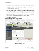
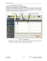
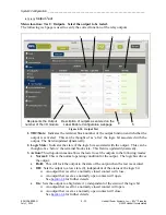
Logic Bit:
The bit range is between 3 and 511 inclusive for logic bits and 1 and 63
inclusive for HMI bits.
5.
Active:
Selects the logic bit state that will make the LED color active.
4.11
System Alarms Status and Configuration
The modules in the HPS/RFL GARD Pro system continually perform self-diagnostics. For
different conditions a module may issue either a major or minor alarm. An example status screen
is shown below followed by details on configuring the system alarms.
4.11.1 System Alarm Status
Menu location: Status > Alarms.
Clicking directly on these buttons will link
to the status page for the module
1
3
2
4
5
6
Figure 4-33. Alarm Status
General:
1.
Inventory Mismatch:
The alarm will become active when a module is removed from or
moved to a different slot in the chassis or inserted into a vacant slot. The alarm will also


