


Power Line Carrier ____________________________________________________________________
RF-MCGARDPRO
Hubbell Power Systems, Inc.
–
RFL™
Products
July 1, 2022
©2022 Hubbell Incorporated
5-60
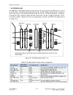
Table 5-24 TX Filter Setup Jumpers
Jumper
Function
J1 and J45
Used to select 8kHz or 16kHz Tx Filter bandwidth.
Both jumpers must be set to 8kHz to select 8kHz bandwidth.
Both jumpers must be set to 16kHz to select 16kHz bandwidth.
J44
Used to select Normal or Test operation.
Set to Normal position for normal system operation.
Set to Test position to move the T1 Test Point from one coil to another during
system testing. Used for tuning the air core inductors L1 and l2.
J1 to J13, and
J15 to J43
Used to tune the center frequency of the Tx Filter from 24kHz to 496kHz. The
outer edges are 20kHz and 500kHz. Tuning the filter is done from the 9508 Filter
Calculation Macro.
For example, for a center frequency of 90kHz, the following jumpers should be
installed: J3, 5, 6, 8, 10, 11, 18, 20, 23, 24, 34, 35, 37 and 38
Transmit Tuning Procedure
1. Use the 9508 TX Filter Programming Sheet (9508 TX Filter Programming Sheet.xls) to
determine jumper settings.
2. Set jumpers as shown.
3. Connect a frequency selective voltmeter to TP1 and TP2 of the Line Board.
4. Apply a sine wave at the center frequency, at a low amplitude (>10VRMS) to the filter input.
5. Set Jumper J44 in the “Norm” position.
6. Make sure the FSVM has a termination of 50 Ohms or use an external termination in parallel
across TP1-TP2.
7. Make sure the inductor locking screws (on inductor, inside shield) are not fully tightened.
8. Adjust L1 for a minimum level on the meter. If a null is not seen, the lowest value of the first
series capacitance may have to be varied.
9. Set Jumper J44 to the “Test” position.
10. Adjust L2 for a minimum level on the meter. If a null is not seen, the lowest value of the
second series capacitance may have to be varied.


