System Configuration __________________________________________________________________
RF-MCGARDPRO
Hubbell Power Systems, Inc.
–
RFL™
Products
July 1, 2022
©2022 Hubbell Incorporated
4-33
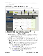
The description column in this dialog will indicate the state of the LED with its assigned color.
The control logic in the next column can be set as required by the user with its associated logic
bit that can be driven either high or low. Once all the changes are made click “Save” to make the
changes permanent. A confirmation window will appear at the bottom right of the web page.
Note:
Virtual LED’s are provided for viewing on the optional touch screen display.
Set the global LED label first
by typing directly in the field
1
2
3
4
5
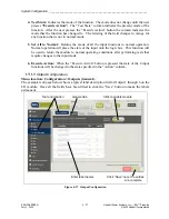
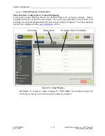
Figure 4-32. LED Configuration
1.
LED:
Indicates the LED color in descending priority.
2.
Description:
The LED active state. In the example shown the LED will turn red when
“HMIOUT Bit 7” is high.
If multiple conditions are true, the LEDs will be displayed with the following priorities.
Table 4-4 LED Priorities
None
Highest
Red
Amber
Green
Lowest
3.
HMI/Logic:
This drop-down menu will allow the user to set the control logic to the
following:
•
None
•
Logic
•
HmiIn
•
HmiOut


