Digital Communications Interfaces ________________________________________________________
RF-MCGARDPRO
Hubbell Power Systems, Inc.
–
RFL™
Products
July 1, 2022
©2022 Hubbell Incorporated
7-9
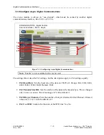
7.2.6 Configure G.703 Digital Communications
1
2
CONFIGURATION > Digital Comms
Comms Interface > Slot # - G703
Figure 7-9. Configuring G.703 Digital Communications
Note
: For G.703/64k, the “module”, or at least the functionality, may be installed on the LED
display card or on the Digital Comms base.
If this settings “bar” represents the on-board functionality of the LED display card, then the title
here will read:
•
“SLOT 2 (FRONT) – G.703/64k” for 3RU
•
“SLOT 9 (FRONT) – G.703/64k” for 6RU
Installed on a Digital Comms base and inserted in a rear slot the settings bar will read:
•
“SLOT # – G.703/64k” for 6RU where # is the rear slot number
The image shows the slot name for a rear mounted Digital Module.
1.
Mode
: This setting is usually set to “Normal”. If set to “Aux-channel”, the G.703 module
becomes a timeslot function in the “Timeslots > Bus 1 or Timeslots > Bus 2”
configuration page. The G.703 payload can then be mapped to a timeslot of another
interface.
2.
Octet Timing
: Controls the Octet timing setting of the G.703 module. Octet Timing is
normally “Disabled” but can be “Enabled”.


