


Power Line Carrier ____________________________________________________________________
RF-MCGARDPRO
Hubbell Power Systems, Inc.
–
RFL™
Products
July 1, 2022
©2022 Hubbell Incorporated
5-53
External Amp
Connector Board
TX
Filter
Power Amp
Power Supply
Motherboard
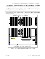
50W Power Amp (Mounted On Front Door,
Not Shown For Clarity)
Figure 5-31. Additional 50W Module in 100W Systems
Setting Jumpers and Switches on the 50W Power Amplifier Circuit Board
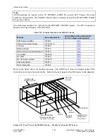
Location of 50W
Power Amp Module
Figure 5-32. Location of 50W Power Amplifier Module
The 50W Power Amplifier has a circuit board which contains two programmable jumpers, J6 and
J7. In addition to this, the board has five connectors (J1, J2, J3, J4, J5), and five potentiometers
(R8, R14, R69, R74, R83) that must be set for proper system operation. These components can
be seen below. Table 5-6 describes the functions of these components and indicates how the
jumpers and potentiometers must be set.
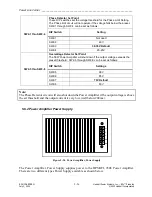
Two DIP Switch banks SW1 and SW2 have been added to the Power Amp Circuit Board. These
switches are factory set for optimum operation but can be changed in the field if required. See
for a description of the switch functions and their settings.


